


LSN Peripherals | LSN Expansion Modules | 371
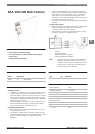
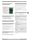
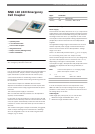
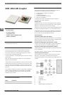
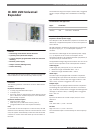
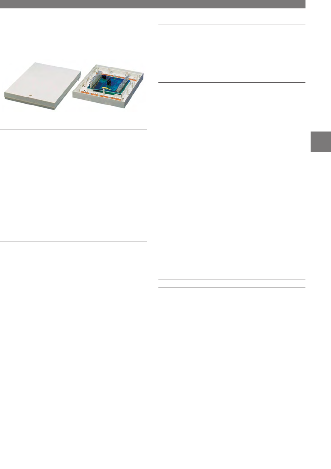
NNK 110 LSN Emergency
Call Coupler
Features
▶
4 primary lines
▶
1 non-monitored line
▶
3 free control outputs
▶
Integrated buzzer
▶
Tamper contact (sabotage alert)
▶
Surface installation
The NNK 110 LSN emergency call coupler is used to connect
GLT emergency call units to the LSN.
Functions
Four programmable primary lines that are programmable as
hold-up, intrusion, tamper, closure monitoring or other
types of detection (can also be used as control input).
A non-monitored line for monitoring closure to obtain
forced system actuation when arming monitoring areas can
be connected.
Three control outputs are available whose function
depends on the detectors attached. Control outputs that
are not needed can be freely programmed with the panel
functions.
The external power supply is monitored.
Max. four KR 100 LSN relay modules for LSN expanders
(option) can be installed.
In the event of wire interruptions or short-circuits, all LSN
elements in the LSN loop continue to be monitored. In this
case, the system automatically creates two stub lines that
continue to monitor from both sides up to the location of
the fault.
The module housing has a tamper contact that, if triggered,
sends a unique message and is evaluated as a sabotage
alert. An integrated buzzer can be used to signal status
changes (e.g. for tests).
Certifications and Approvals
Region Certification
Europe CE NNK 100 LSN
Germany VdS G 102069, C NNK 110 LSN
Installation/Configuration Notes
Power supply
A second twin wire lead, referred to as +V/-V, is required to
supply power to the remaining expansion module functions
and any connected conventional emergency call detectors.
The length of the twin wire +V/-V depends on the current
consumption of the LSN expanders being supplied and their
peripherals, insofar as these do not have independent
supplies.
The applicable voltage range must be taken into account
and the required power supply must be determined to
ensure correct function of the LSN expanders. Voltage
range: 9 V to 30 V.
There is an electrically isolated output, V
0
=12 V, to supply
12 V consuming units (note max. output current).
As the terminal voltage can be 28 V or 12 V, the voltage drop
up to the LSN expander can be a maximum of 6 V or 3 V,
depending on the type of LSN expander. If current
consumption is high, LSN expanders and peripherals can be
supplied via a separate line with a larger diameter, if
necessary.
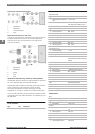
Note Current consumption L in at varying supply
power and output current L out
+V L in
where L out = 0 mA
L in
where L out = 100 mA
9 V 7 mA 240 mA
12 V 7 mA 160 mA
30 V 13 mA 70 mA
In order to keep the total current requirement of the
NNK 110 LSN low, the input voltage must be as high as
possible. For this reason, it is essential to take account of
the voltage drop on the line.
Cable lengths
Cable length per primary line (PL) or control lines
•
Maximum length unshielded cable – 10 m
•
Maximum length shielded cable – 500 m
www.boschsecurity.com Bosch Security Systems B.V.
6