


238 | Detectors and Accessories | Smoke
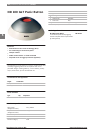
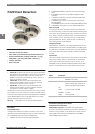
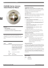
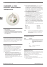
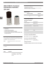
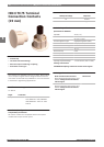
F220‑B6RS 24 VDC
Four‑wire Detector Base
with Sounder
Features
▶
Easy installation
▶
Interchangeable detector heads
▶
UL listed when used with F220 Series Detector Heads
▶
UL464 approved sounder driven by the detector head
or the NAC circuit
The F220‑B6RS 24 VDC Four-wire Detector Base with
Sounder meets the requirements of UL464 for a notification
device and works with the F220 Series Photoelectric Smoke
and Heat Detectors. Power the sounder from the control
panel's NAC circuit or from auxiliary power.
Functions
Sounder Configuration
The output (sound pattern and synchronization) of the
sounders on a detection loop can be configured in four
different ways. Refer to the F220 Series Detectors
Installation Instructions (P/N: 4998138694) for instructions
on wiring and setting the F220‑B6RS detector base for
these configurations:
1. NAC Follower (Direct Wire) Configuration: In this
configuration, the sounders on the loop follow the
signal on the NAC terminals as programmed at the
control panel. Refer to the control panel's installation
manual for NAC configuration instructions. This
configuration requires an extra pair of supervised wires
for the sounder circuit.
2.
Reverse Polarity Configuration: In this configuration
(not suitable for synchronized protocols; such as,
Cooper Wheelock, Gentex, or System Sensor), the
sounders in a loop activate due to reversed polarity on
the power line. The output pattern is not controlled by
the base in this operating mode; it follows the reversing
power signal on the detector head's terminals as
programmed at the control panel.
3. Local Annunciation Configuration: In this
configuration, each sounder is individually set for one
of the following patterns: Temporal (Code 3), March
Time, or Continuous Tone. Use a D275 Power
Supervision Module in this configuration to supervise
the detector loop.
4. Interconnection Configuration: In this configuration,
up to five detectors supervise the end of the detector
loop when interconnected by a common wire. All
sounders within the group activate together. Set all
units for the same output pattern (Temporal [Code 3],
March Time, or Continuous Tone). All interconnected
detectors are synchronized with and sound the pattern
of the originating detector.
The maximum wire length for connecting up to five units
is:
Wire Size Wire Length
18 AWG (1.2 mm) 300 ft (91 m)
16 AWG (1.5 mm) 450 ft (137 m)
14 AWG (1.8 mm) 750 ft (229 m)
Note To ensure interconnected units can signal an
alarm, the line load after the last detector on
the interconnected detector loop must not
exceed 10 mA.
Certifications and Approvals
Region Certification
USA UL ULSZ: Audible Signal Appliances (UL464),
UROX: Smoke - Automatic Fire Dectectors
(UL268), UROX7: Smoke - Automatic Fire
Dectectors Certified for Canada (ULC-
S529)
FM
CSFM 1700-1615: 105 July 2008
NYC-MEA (117-05-E)
Installation/Configuration Notes
Compatibility Information
Four‑wire: Compatible with all UL Listed four‑wire control
panels. Refer to the control panel's Installation Instructions
for proper end‑of‑line (EOL) resistor selection.
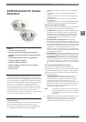
Detectors: Compatible with the following F220 Series
Detector Heads:
•
F220‑P Photoelectric Smoke Detector
•
F220‑PTH Photoelectric Smoke Detector with +135°F
(+57°C) Heat Sensor
Bosch Security Systems B.V. www.boschsecurity.com
5