


442 | Wireless Local Security Network (wLSN) | wLSN Peripherie
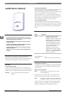
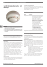
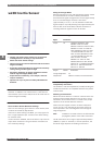
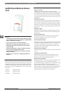
wLSN Inertia Sensor
Features
▶
Holding clip allows sensor pivoting in any direction
enabling detector mounting in any orientation
▶
Minor and Gross Attack settings
▶
Option of using an internal reed switch with an external
magnet assembly
▶
Externally-visible LED indicates operational sensitivity
setting testing and RF signal strength
▶
Determine suitability of chosen installation location
with RF Signal Strength (RFSS) mode
▶
Supervised for low-battery, cover-tamper, and wall-
tamper conditions
▶
Operates for up to 5 years on readily-obtainable AA
batteries
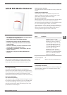
The wLSN Inertia Detector is used for monitoring doors and
windows. In addition to an inertia sensor, it has internal
reed switches (one on each side) that can be used with an
external magnet assembly.
Functions
Gross or Minor Attack Movement Settings
There are two settings (gross attack or minor attack) each
of which has sensitivity adjustments.
If the minor attack setting is enabled, you can program for
four or eight repetitive taps. Use the minor attack setting
for sensitive areas.
If minor attack is disabled, the inertia sensor only reacts to
major attack movement. The gross attack movement has
four sensitivity settings.
RF Signal Strength Mode
Removing the device cover and pressing the tamper switch
four times within 10 seconds of battery installation
activates the RF signal strength mode. The LED lights steady
for 5 sec and then begins to flash. A slow flash
(approximately 1 sec on, 1 sec off) indicates insufficient
signal reception. A quickly flashing LED (approximately five
times as fast as the slow flash) indicates the device is
receiving sufficient signal from the wLSN Hub.
Certifications and Approvals
Region Certification
Europe CE 1999/5/EC, IEC60950-1: 2001,
EN60950-1:2001 +A11:2004,
EN50130-4: 1996 +A1: 1998 +A2: 2003,
EN61000-4-2: 1995 +A1: 1998 +A2:
2001, EN61000-4-3: 2002 +A1: 2003
+A2: 2005, EN61000-4-4: 1995 +A1:
2001 +A2: 2001, EN61000-4-5: 1995
+A1: 2001, EN61000-4-6: 1996 +A1:
2001 +A2: 2001 +A3: 2005,
EN61000-4-11: 1994 +A1: 2001,
EN55022/ANSI C63.4: 2003, ETSI EN
300 220-1 V1.3.1: 2000-09, ETSI EN 301
489-1 V1.4.1: 2002-08, ETSI EN 301
489-3 V1.4.1: 2002-08
Belgium INCERT B-509-0056
Listings and Approvals:
X
Complies with: EN50131-1 Grade 2, Environmental class II
Installation/Configuration Notes
Compatibility Information
The wireless Local SecurityNetwork (wLSN) including the
wLSN Inertia Detector is compatible with the Easy Series
Control Panel.
Mounting Considerations
Mount the inertia detector on interior surfaces where it is
protected from weather elements such as rain or snow.
Orientation of the inertia sensor is critical to the proper
operation of the inertia detection function.
When used, the magnet must be no farther away than
12 mm (0.5 in.) from the body of the inertia sensor for
normal operation. The mounting base has markings for
magnet alignment.
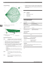
Note Installation on metal surfaces can affect the RF
propagation pattern of the radio transceiver.
The RF transceiver has a range of approximately 1000 m
(3000 ft) in open air. However, in normal operation, the
actual RF range depends on building construction.
Bosch Security Systems B.V. www.boschsecurity.com
8