


3 - 27
Chapter 3 Specifications and Functions
3.4.3 List of input signal details
The details of each external input connection connector of Simple Motion module are
shown below.
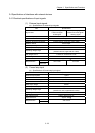
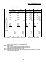
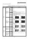
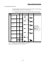
Signal name Pin No. Signal details
Differential-
output type
Manual pulse
generator/Incremental
synchronous encoder
A phase/PLS
HAH
(A+)
1A17
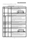
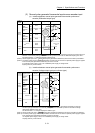
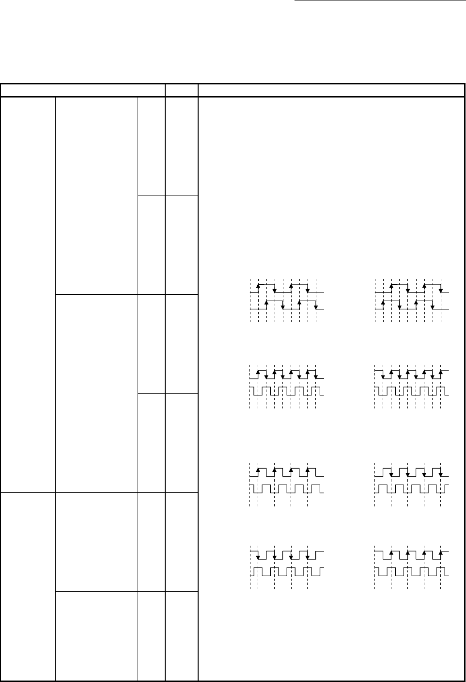
(1) Phase A/Phase B
• Input the pulse signal from the manual pulse generator/incremental
synchronous encoder A phase and B phase.
• If the A phase leads the B phase, the positioning address will increase at
the rising and falling edges of each phase.
• If the B phase leads the A phase, the positioning address will decrease at
the rising and falling edges of each phase.
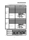
(a) Magnification by 4
[When increased] [When decreased]
Positioning
address
Positioning
address
+1 +1+1+1+1+1+1+1 -1 -1-1 -1 -1 -1 -1 -1
A phase
B phase
A phase
B phase
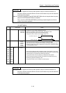
(b) Magnification by 2
[When increased] [When decreased]
Positioning
address
Positioning
address
+1 +1 +1 +1 -1-1 -1 -1
A phase
B phase
A phase
B phase
+1 +1 +1 +1 -1-1 -1 -1
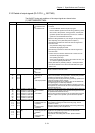
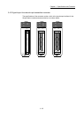
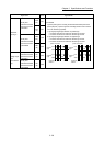
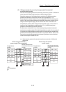
(c) Magnification by 1
1) Positive logic
[When increased] [When decreased]
Positioning
address
Positioning
address
+1 +1 +1 +1 -1-1 -1 -1
A phase
B phase
A phase
B phase
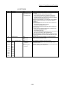
2) Negative logic
[When increased] [When decreased]
Positioning
address
Positioning
address
+1 +1 +1 +1 -1-1 -1 -1
A phase
B phase
A phase
B phase
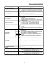
HAL
(A-)
1B17
Manual pulse
generator/Incremental
synchronous encoder
B phase/SIGN
HBH
(B+)
1A18
HBL
(B-)
1B18
Voltage-output
type/
open-collector
type
Manual pulse
generator/Incremental
synchronous encoder
A phase/PLS
HA
(A)
1B19
Manual pulse
generator/Incremental
synchronous encoder
B phase/SIGN
HB
(B)
1B20