


16 - 3
Chapter 16 Troubleshooting
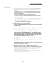
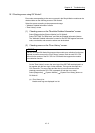
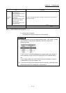
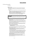
(b) Error and Solution, Intelligent Module Information
• Error and Solution
Details of the selected in the "Error History List" and its corrective action
are displayed.
• Intelligent Module Information
The status of Simple Motion module when the error selected in the "Error
History List" occurred is displayed.
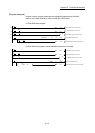
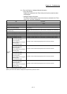
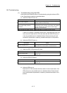
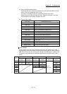
Item Description
Start axis The axis No. requested to start is stored.
Positioning start No.
The start No. at positioning start is stored.
(Note-1)
Axis in which the error occurred The axis No. in which the error occurred is stored.
Axis error occurrence (Data No.)
The positioning data No. currently being executed in which the error occurred is stored.
(Note-1), (Note-2)
Current feed value
The current feed value of the axis in which the error occurred (at error occurrence) is
stored.
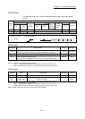
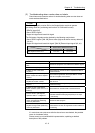
State of the input signal [X0 to XF] The status of input signals [X0 to XF] (at error occurrence) is stored (in binary).
State of the input signal [X10 to X1F] The status of input signals [X10 to X1F] (at error occurrence) is stored (in binary).
State of the output signal [Y0 to YF] The status of output signals [Y0 to YF] (at error occurrence) is stored (in binary).
State of the output signal [Y10 to Y1F] The status of output signals [Y10 to Y1F] (at error occurrence) is stored (in binary).
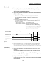
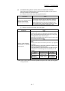
QD77MS4
display
• Axis 1 upper limit signal
• Axis 1 lower limit signal
• Axis 1 stop signal
• Axis 1 external command signal/
switching signal
• Axis 1 near-point signal
The status of axis 1 external input signals (at error occurrence) is stored.
• Axis 2 upper limit signal
• Axis 2 lower limit signal
• Axis 2 stop signal
• Axis 2 external command signal/
switching signal
• Axis 2 near-point signal
The status of axis 2 external input signals (at error occurrence) is stored.
• Axis 3 upper limit signal
• Axis 3 lower limit signal
• Axis 3 stop signal
• Axis 3 external command signal/
switching signal
• Axis 3 near-point signal
The status of axis 3 external input signals (at error occurrence) is stored.
• Axis 4 upper limit signal
• Axis 4 lower limit signal
• Axis 4 stop signal
• Axis 4 external command signal/
switching signal
• Axis 4 near-point signal
The status of axis 4 external input signals (at error occurrence) is stored.
(Note-1): "0" is stored at the servo error occurrence.
(Note-2): The current cam data No. is displayed for output axis of synchronous control.