


7 - 2
Chapter 7 Memory Configuration and Data Process
7.1 Configuration and roles of QD77MS memory
7.1.1 Configuration and roles of QD77MS memory
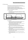
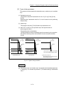
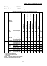
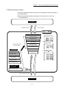
The Simple Motion module is configured of the following four memories.
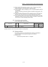
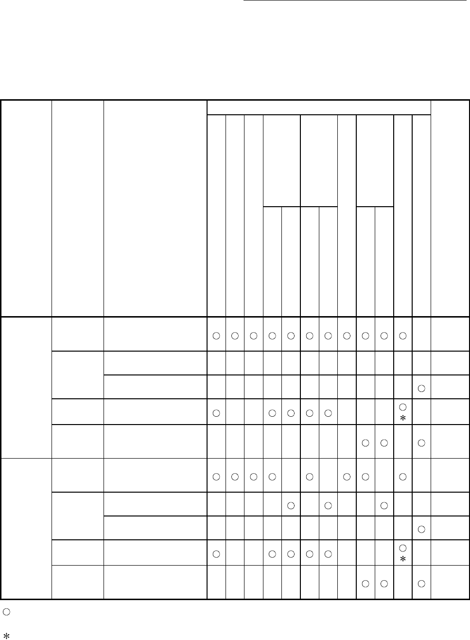
Model
Memory
configuration
Role
Area configuration
Backup
Parameter area
Monitor data area
Control data area
Positioning data area
Block start data area
PLC CPU memo area
Servo parameter area
Synchronous control area
Cam area
(No. 1 to 100)
(No. 101 to 600)
(No.7000 to 7001)
(No.7002 to 7004)
([Pr.100], PA, PB, PC)
(
PA19, PD, PE, PS, PF, Po, PL)
QD77MS2
QD77MS4
Buffer
memory
Area that can be directly
accessed with sequence
program with PLC CPU.
–
Not
possible
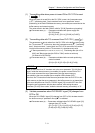
Internal
memory
Area that can be set only
with GX Works2.
––––––––– – – –
Not
possible
Area that can be set only
using buffer memory.
––––––––– – –
Not
possible
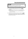
Flash ROM
Area for backing up data
required for positioning.
–– –– –
– Possible
Internal
memory
(nonvolatile)
Area for backing up servo
parameter or cam data.
––––––––
–
Possible
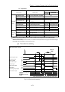
QD77MS16
Buffer
memory
Area that can be directly
accessed with sequence
program with PLC CPU.
– –
–
–
Not
possible
Internal
memory
Area that can be set only
with GX Works2.
––––
– ––
– –
Not
possible
Area that can be set only
using buffer memory.
––––––––– – –
Not
possible
Flash ROM
Area for backing up data
required for positioning.
–– –– –
– Possible
Internal
memory
(nonvolatile)
Area for backing up servo
parameter or cam data.
––––––––
–
Possible
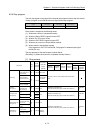
: Setting and storage area provided
– : Setting and storage area not provided
: Parameter only
Possible : Data is held even when power is turned OFF.
Not possible: Data is lost when power is turned OFF.