11 - 17
Chapter 11 Manual Control
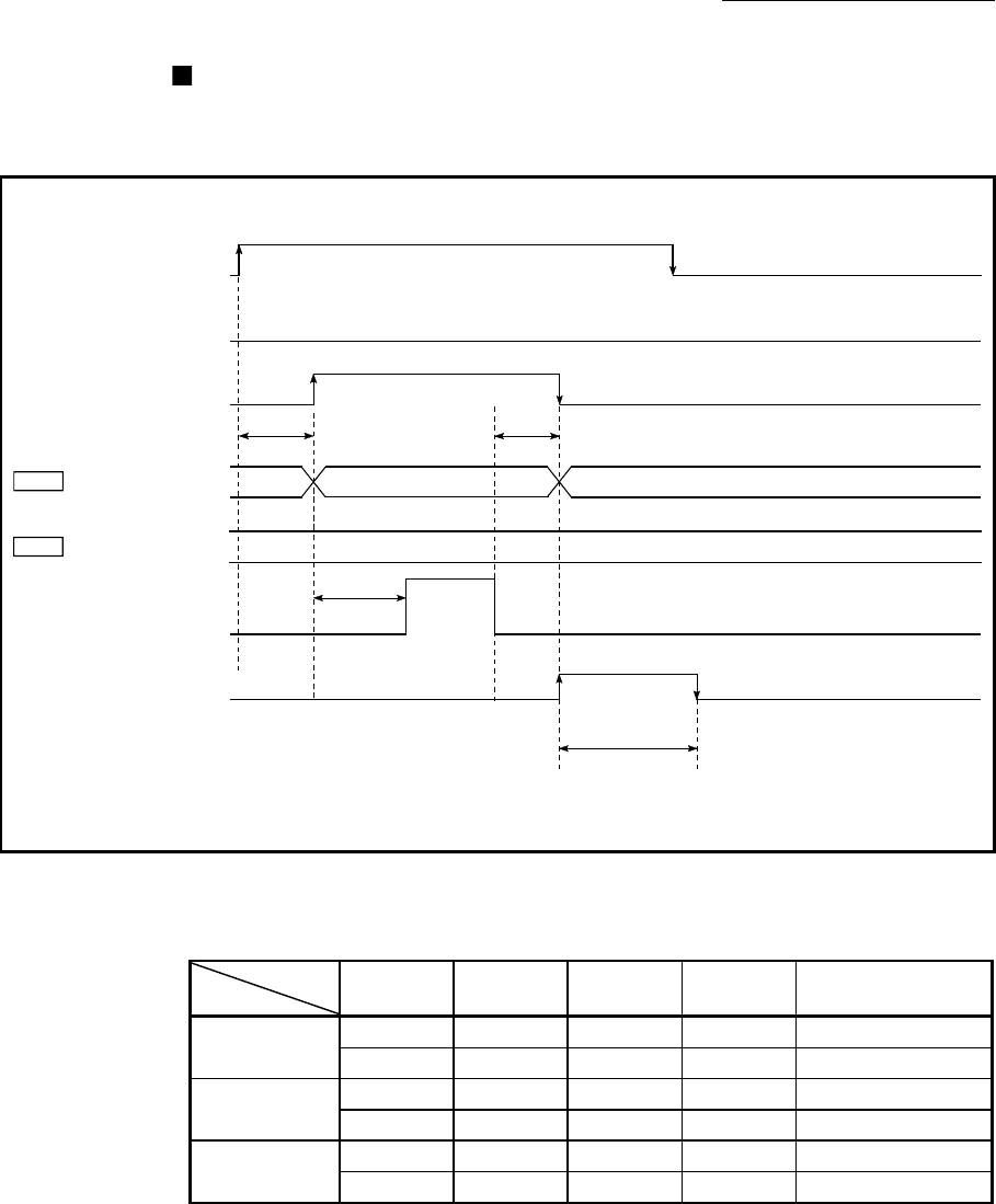
Inching operation timing and processing times
The following drawing shows the details of the inching operation timing and
processing time.
[QD77MS4 operation example]
ON
t4
OFF
OFF
OFF
OFF
Reverse run JOG start signal
[Y9, YB, YD, YF]
BUSY signal
[XC, XD, XE, XF]
Forward run JOG start signal
[Y8, YA, YC, YE]
Axis operation
status
Md.26
Positioning operation
Positioning complete
signal
[X14, X15, X16, X17]
Inching movement
amount
Cd.16
JOG operation (3)
t1
ON
ON
t3
Standby (0)
t2
*
1
Arbitary value
Standby (0)
*1: "JOG operation" is set in "[Md.26] Axis operation status" even during inching operation.
(Note): Refer to Section 3.3 for input/output signal of QD77MS16.
Fig. 11.12 Inching operation timing and processing times
Normal timing times Unit : [ms]
Operation
cycle
t1 t2 t3 t4
QD77MS2
0.88 0.4 to 0.9 1.8 to 2.7 0 to 0.9 Follows parameters
1.77 0.4 to 1.4 3.2 to 3.9 0 to 1.8 Follows parameters
QD77MS4
0.88 0.4 to 0.9 1.8 to 2.7 0 to 0.9 Follows parameters
1.77 0.4 to 1.4 3.2 to 3.9 0 to 1.8 Follows parameters
QD77MS16
0.88 0.4 to 0.9 1.8 to 2.7 0 to 0.9 Follows parameters
1.77 0.8 to 1.4 3.2 to 3.9 0 to 1.8 Follows parameters
Depending on the operating statuses of the other axes, delay may occur in the
t1 timing time.


