


13 - 41
Chapter 13 Control Sub Functions
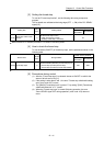
[3] Setting the forced stop
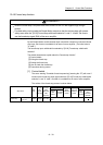
To use the "Forced stop function", set the following data using a sequence
program.
The set details are validated at the rising edge (OFF
ON) of the PLC READY
signal [Y0].
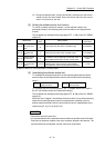
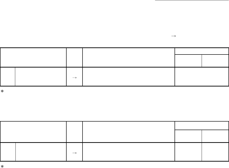
Setting item
Setting
value
Setting details
Buffer memory address
QD77MS2
QD77MS4
QD77MS16
[Pr.82]
Forced stop valid/ invalid
selection
Set the forced stop function.
0: Valid (Forced stop is used)
1: Invalid (Forced stop is not used)
35
:
Refer to Section 5.2.3 "Detailed parameters 1" for details on the setting details.
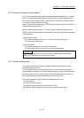
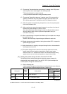
[4] How to check the forced stop
To use the states (ON/OFF) of forced stop input, set the parameters shown in the
following table.
Monitor item
Monitor
value
Storage details
Buffer memory address
QD77MS2
QD77MS4
QD77MS16
[Md.50] Forced stop input
Stores the states (ON/OFF) of forced stop input.
0: Forced stop input ON (Forced stop)
1: Forced stop input OFF (Forced stop release)
1431 4231
:
Refer to Section 5.6.1 "System monitor data" for details on the storage details.
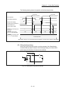
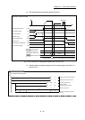
[5] Precautions during control
(1) After the "Forced stop input" is released, the servo ON/OFF is valid for the
status of all axis servo ON [Y1].
(2) If the setting is other than 0 and 1, the error "Forced stop valid/invalid setting
error" (error code: 937) occurs.
(3) The "[Md.50] Forced stop input" is stored "1" by setting "[Pr.82] Forced stop
valid/invalid selection" to "1: invalid".
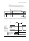
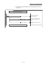
(4) When the "Forced stop input" is turned ON during operation, the error
"Servo READY signal OFF during operation" (error code: 102) does not
occur.