


16 - 17
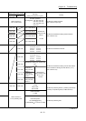
Chapter 16 Troubleshooting
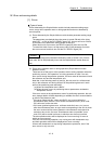
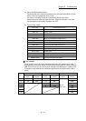
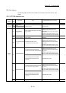
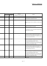
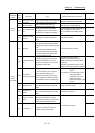
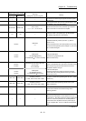
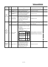
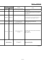
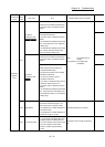
Related buffer memory address
Set range
(Setting with sequence program)
Remedy
QD77MS2
QD77MS4
QD77MS16
— — — —
— — — Check that there is no influence from noise.
— — —
Review the program which turns ON/OFF PLC READY signal
[Y0].
— — —
Check the servo amplifier power, wiring with the servo
amplifier, and connection of connectors.
— — —
Check that there is no error on the personal computer side I/F
to which a cable is connected.
— — —
After making an axis error reset (refer to [3] in Section 16.3),
perform manual control operation (refer to Chapter 11) to
move the axis to the other position in order that the upper
limit signal (FLS) will not turn OFF.
— — —
• Check the wiring of upper limit signal FLS.
• Check if the specification of the limit switch and the setting of
the "[Pr.22] Input signal logic selection" match.
• If hardware stroke limit (limit switch) is unnecessary system
for installation, wire to always turn ON the upper limit signal
(FLS) input of the Simple Motion module.
— — —
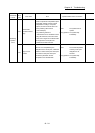
After making an axis error reset (refer to [3] in Section 16.3),
perform manual control operation (refer to Chapter 11) to
move the axis to the other position in order that the lower
limit signal (RLS) will not turn OFF.
— — —
• Check the wiring of lower limit signal RLS.
• Check if the specification of the limit switch and the setting of
the "[Pr.22] Input signal logic selection" match.
• If hardware stroke limit (limit switch) is unnecessary system
for installation, wire to always turn ON the lower limit signal
(RLS) input of the Simple Motion module.
— — —
After confirming the stop command status, then review the
timing of start.