


14 - 29
Chapter 14 Common Functions
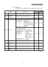
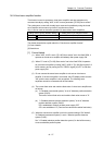
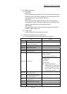
[2] Restrictions
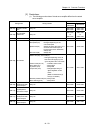
(1) The following monitor data of virtual servo amplifier differ from the actual
servo amplifier.
Storage item Storage details
Buffer memory address
QD77MS2
QD77MS4
QD77MS16
[Md.102]
Deviation counter
value
Always "0".
852+100n
853+100n
2452+100n
2453+100n
[Md.106]
Servo amplifier
software No.
Always "0".
864+100n
to
869+100n
2464+100n
to
2469+100n
[Md.107] Parameter error No. Always "0". 870+100n 2470+100n
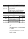
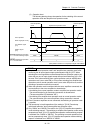
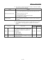
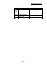
[Md.108] Servo status
• Zero point pass (b0) : Always ON
• Zero speed (b3) : Changed depending on the
command speed
• Speed limit (b4) : Always ON when other than "0" is
set to the command torque at
torque control mode. Otherwise,
always OFF.
• PID control (b8) : Always OFF
876+100n 2476+100n
• READY ON (b0), Servo ON (b1)
: Changed depending on the all
axis servo ON signal [Y1] and
"[Cd.100] Servo OFF command"
• Control mode (b2, b3) : Indicates control mode.
• Servo alarm (b7) : Always OFF
• In-position (b12) : Always ON
• Torque limit (b13) : Changed depending on
"[Md.104] Motor current
value".
(Refer to "Restrictions (2)
and (3)" for details.)
• Absolute position lost (b14): Always OFF
• Servo warning (b15) : Always OFF
877+100n 2477+100n
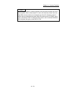
[Md.109]
Regenerative load
ratio/Optional data
monitor output 1
Always "0". 878+100n 2478+100n
[Md.110]
Effective load
torque/Optional
data monitor output
2
Always "0". 879+100n 2479+100n
[Md.111]
Peak torque
ratio/Optional data
monitor output 3
Always "0". 880+100n 2480+100n
[Md.112]
Optional data
monitor output 4
Always "0". 881+100n 2481+100n
n: Axis No.-1