


7 - 8
Chapter 7 Memory Configuration and Data Process
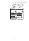
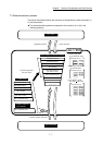
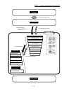
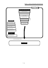
(1) Transmitting data when power is turned ON or PLC CPU is reset
( )
When the power is turned ON or the PLC CPU is reset, the "parameters area
(c)
1
", "positioning data", "block start data" and "servo parameter" stored
(backed up) in the flash ROM/internal memory (nonvolatile) are transmitted to the
buffer memory and internal memory.
The value stored in the flash ROM is valid for "[Pr.96] Operation cycle setting".
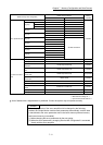
1: Parameter area (c) ...... Parameters validated with power supply ON/
PLC CPU reset.
([Pr.96], [Pr.97], [Pr.114], [Pr.800] to [Pr.807])
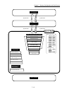
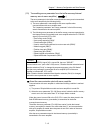
(2) Transmitting data with TO command from PLC CPU ( )
The parameters or data is written from the PLC CPU to the buffer memory using
the TO command
2
. At this time, when the "parameter area (b)
3
", "positioning
data", "block start data", "control data" and "PLC CPU memo area" are written
into the buffer memory with the TO command, it is simultaneously valid.
2: "Servo parameter (PA19, PD, PE, PS, PF, Po, PL)", "Positioning data (No.101 to
600)" and "Block start data (No.7002 to 7004)" can be set with only
GX Works2 in QD77MS16.
3: Parameter area (b) ..... Parameters validated with next each positioning
control is started.
([Pr.8] to [Pr.10], [Pr.25] to [Pr.42], [Pr.84])
POINT
When a value other than "0" has been set to the servo parameter "[Pr.100] Servo
series" inside the internal memory (nonvolatile), the power is turned ON or PLC
CPU is reset to transmit the servo parameter inside the internal memory
(nonvolatile) to the servo amplifier (servo amplifier LED indicates "b").
After that, the TO instruction writes the servo parameter from the PLC CPU to the
buffer memory so that the servo parameter in the buffer memory is not transmitted
to the servo amplifier even if the PLC READY signal [Y0] is turned OFF then ON.
Change the servo parameter with the above method, after setting the servo
parameter "[Pr.100]
Servo series" inside the internal memory (nonvolatile), to "0".
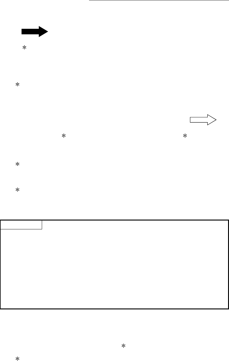
(3) Validate parameters when PLC READY signal [Y0] changes from
OFF to ON
When the PLC READY signal [Y0] changes from OFF to ON, the data stored in
the buffer memory's "parameter area (a)
4
" is validated.
4: Parameter area (a) .... Parameters validated when PLC READY signal [Y0]
changes from OFF to ON.
([Pr.1] to [Pr.7], [Pr.11] to [Pr.24], [Pr.43] to [Pr.57],
[Pr.80] to [Pr.83], [Pr.89] to [Pr.95])