


14 - 45
Chapter 14 Common Functions
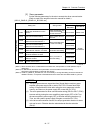
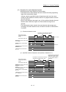
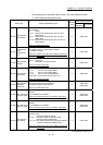
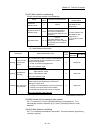
The following shows the buffer memory used in the mark detection function.
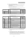
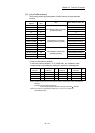
(1) Mark detection setting parameters
Setting item Setting details/setting value
Default
value
Buffer memory address
QD77MS2
QD77MS4
QD77MS16
[Pr.800]
Mark detection
signal setting
Set the external input signal (high speed input request) for
mark detection.
0 : Invalid
1 to 2 : External command signal of axis 1 to axis 2
(QD77MS2)
1 to 4 : External command signal of axis 1 to axis 4
(QD77MS4)
1 to 16 : External command signal of axis 1 to axis 16
(QD77MS16)
Fetch cycle: Power supply ON
0 54000+20k
[Pr.801]
Mark detection
signal
compensation
time
Set the compensation time such as delay of sensor.
Set a positive value to compensate for a delay.
-32768 to 32767[µs]
Fetch cycle: Power supply ON or PLC READY signal [Y0]
OFF to ON
0 54001+20k
[Pr.802]
Mark detection
data type
Set the target data for mark detection.
0 to 12 : Data type
-1 : Optional 2 word buffer memory
Fetch cycle: Power supply ON
0 54002+20k
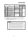
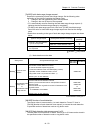
[Pr.803]
Mark detection
data axis No.
Set the axis No. of target data for mark detection.
1 to 2 : Axis 1 to Axis 2 (QD77MS2)
1 to 4 : Axis 1 to Axis 4 (QD77MS4)
1 to 16 : Axis 1 to Axis 16 (QD77MS16)
801 to 804 : Synchronous encoder Axis 1 to 4
Fetch cycle: Power supply ON
0 54003+20k
[Pr.804]
Mark detection
data buffer
memory No.
Set the optional buffer memory No.
Set this parameter as an even number.
0 to 65534: Optional buffer memory
Fetch cycle: Power supply ON
0
54004+20k
54005+20k
[Pr.805]
Latch data range
upper limit value
Set the valid upper limit value for latch data at mark
detection.
-2147483648 to 2147483647
Fetch cycle: Power supply ON, PLC READY signal [Y0]
OFF to ON, or latch data range change request
0
54006+20k
54007+20k
[Pr.806]
Latch data range
lower limit value
Set the valid lower limit value for latch data at mark
detection
-2147483648 to 2147483647
Fetch cycle: Power supply ON, PLC READY signal [Y0]
OFF to ON, or latch data range change request
0
54008+20k
54009+20k
[Pr.807]
Mark detection
mode setting
Set the continuous detection mode or specified number of
detection mode.
0 : Continuous detection mode
1 to 32 : Specified number of detection mode
(Set the number of detections.)
-1 to -32 : Ring buffer mode (Set the value that made the
number of buffers into negative value.)
Fetch cycle: Power supply ON or PLC READY signal [Y0]
OFF to ON
0 54010+20k
k: Mark detection setting No.-1