


5 - 52
Chapter 5 Data Used for Positioning Control
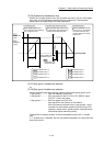
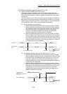
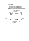
[Pr.95] External command signal selection
QD77MS16
Set the external command signal.
0: Not used ........ External command signal is not used.
1: DI1 ................. DI1 is used as external command signal.
2: DI2 ................. DI2 is used as external command signal.
3: DI3 ................. DI3 is used as external command signal.
4: DI4 ................. DI4 is used as external command signal.
Note) The "External command signal selection" is included in detailed parameters
2, but it will be valid at the rising edge (OFF to ON) of the PLC READY
signal [Y0].
POINT
Same external command signal can be used in the multiple axes.
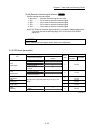
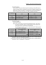
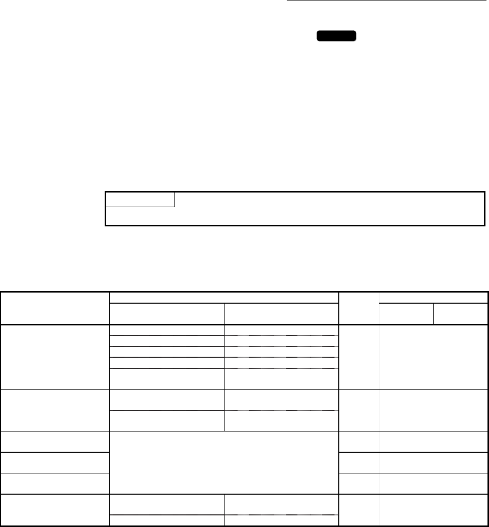
5.2.5 OPR basic parameters
Item
Setting value, setting range
Default
value
Buffer memory address
Value set with GX Works2
Value set with sequence
program
QD77MS2
QD77MS4
QD77MS16
[Pr.43]
OPR method
0 : Near-point dog method 0
0 70+150n
4 : Count method 1) 4
5 : Count method 2) 5
6 : Data set method 6
7 : Scale origin signal detection
method
7
[Pr.44]
OPR direction
0 : Positive direction (address
increment direction)
0
0 71+150n
1 : Negative direction (address
decrement direction)
1
[Pr.45]
OP address
The setting value range differs depending on the "[Pr.1] Unit
setting".
0
72+150n
73+150n
[Pr.46]
OPR speed
1
74+150n
75+150n
[Pr.47]
Creep speed
1
76+150n
77+150n
[Pr.48]
OPR retry
0 : Do not retry OPR with limit
switch
0
0 78+150n
1 : Retry OPR with limit switch 1
n: Axis No.-1