15- 2
Chapter 15 Dedicated Instructions
15.1 List of dedicated instructions
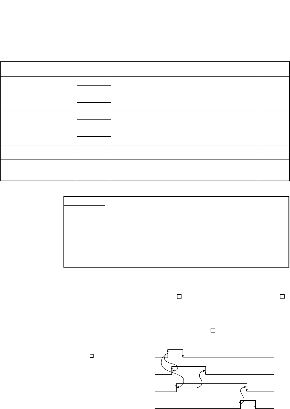
The dedicated instructions explained in this Chapter are listed in Table 15.1.
Table 15.1 List of dedicated instructions
Application
Dedicated
instruction
Outline of functions Reference
Positioning start
ZP.PSTRT1
This function starts the positioning control of the designated
axis of the Simple Motion module.
Section 15.3
ZP.PSTRT2
ZP.PSTRT3
ZP.PSTRT4
Teaching
ZP.TEACH1
This function carries out teaching the designated axis of the
Simple Motion module.
Section 15.4
ZP.TEACH2
ZP.TEACH3
ZP.TEACH4
Writing to flash ROM ZP.PFWRT
This function writes the buffer memory parameters,
positioning data and block start data to the flash ROM.
Section 15.5
Parameter initialization ZP.PINIT
This function initializes the buffer memory and flash ROM
setting data to the factory-set data (initial values of the
Simple Motion module).
Section 15.6
POINT
The dedicated instructions of QD77MS16 can be used for only axis 1 to 4. They
cannot be used for axis 5 to 16. If the ZP.PSTRT5 to ZP.PSTRT16 or ZP.TEACH5
to ZP.TEACH16 is executed, the error "Program code error" (error code: 4002) for
PLC CPU and the error "PLC CPU error" (error code: 803) for QD77MS16 will
occur and positioning cannot be started.
Refer to "QCPU User's Manual (Hardware Design, Maintenance and Inspection) for
error of PLC CPU".
15.2 Interlock during dedicated instruction is executed
The positioning start instruction (ZP.PSTRT ) and teaching instruction (ZP.TEACH )
cannot be executed simultaneously in each axis. If they are executed at the same time,
the second and later instructions are ignored by an internal interlock (no error will
occur).
The timing of the positioning start instruction (ZP.PSTRT
) is as shown below.
ZP.PSTRT instruction ON
Interlock provided by PLC CPU
BUSY signal
Positioning completed signal
OFF
OFF
OFF
OFF
ON
ON
ON
ON


