


11 - 4
Chapter 11 Manual Control
11.2 JOG operation
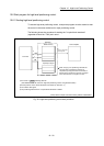
11.2.1 Outline of JOG operation
JOG operation
In JOG operation, the forward run JOG start signal or reverse run JOG start signal
turns ON, causing pulses to be output to the servo amplifier from the Simple
Motion module while the signal is ON. The workpiece is then moved in the
designated direction.
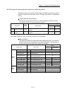
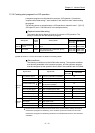
Signal QD77MS2 QD77MS4 QD77MS16
Forward run JOG start signal
Y8, YA Y8, YA, YC, YE
[Cd.181] Forward run JOG start
Reverse run JOG start signal
Y9, YB Y9, YB, YD, YF
[Cd.182] Reverse run JOG start
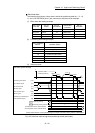
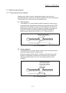
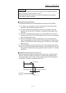
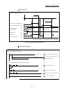
The following shows examples of JOG operation.
1)
When the START signal turns ON, acceleration begins in the direction designated by the
START signal, and continues for the acceleration time designated in "[Pr.32] JOG operation
acceleration time selection". At this time, the BUSY signal changes from OFF to ON.
2)
When the workpiece being accelerated reaches the speed set in "[Cd.17] JOG speed", the
movement continues at this speed. The constant speed movement takes place at 2) and 3).
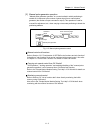
3)
When the START signal is turned OFF, deceleration begins from the speed set in "[Cd.17]
JOG speed", and continues for the deceleration time designated in "[Pr.33] JOG operation
deceleration time selection".
4)
The operation stops when the speed becomes "0". At this time, the BUSY signal changes
from ON to OFF.
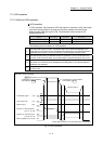
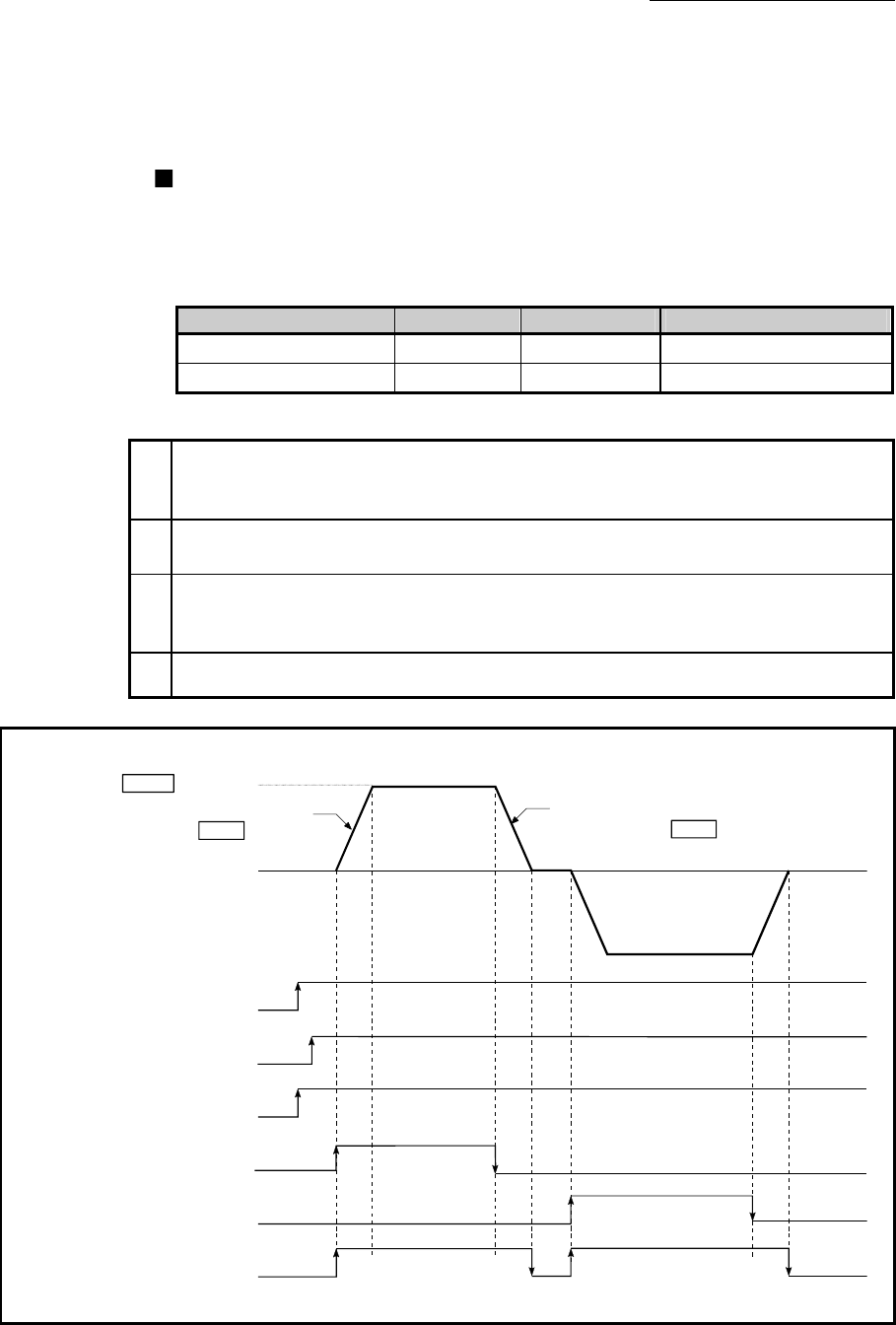
[QD77MS4 operation example]
PLC READY signal [Y0] OFF
ON
Reverse run JOG start signal
[Y9, YB, YD, YF]
OFF
ON
OFF
ON
BUSY signal[XC, XD, XE, XF]
OFF
ON
Forward JOG run
Reverse JOG run
READY signal [X0]
Forward run JOG start signal
[Y8, YA, YC, YE]
Cd. 17 JOG speed
Acceleration for the acceleration
time selected in Pr. 32
Deceleration for the deceleration
time selected in Pr. 33
1) 2) 3) 4)
OFF
ON
All axis servo ON [Y1] OFF
ON
(Note): Refer to Section 3.3 for input/output signal of QD77MS16.
Fig. 11.4 JOG operation