


1 - 21
Chapter 1 Product Outline
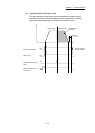
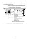
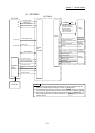
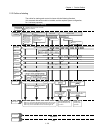
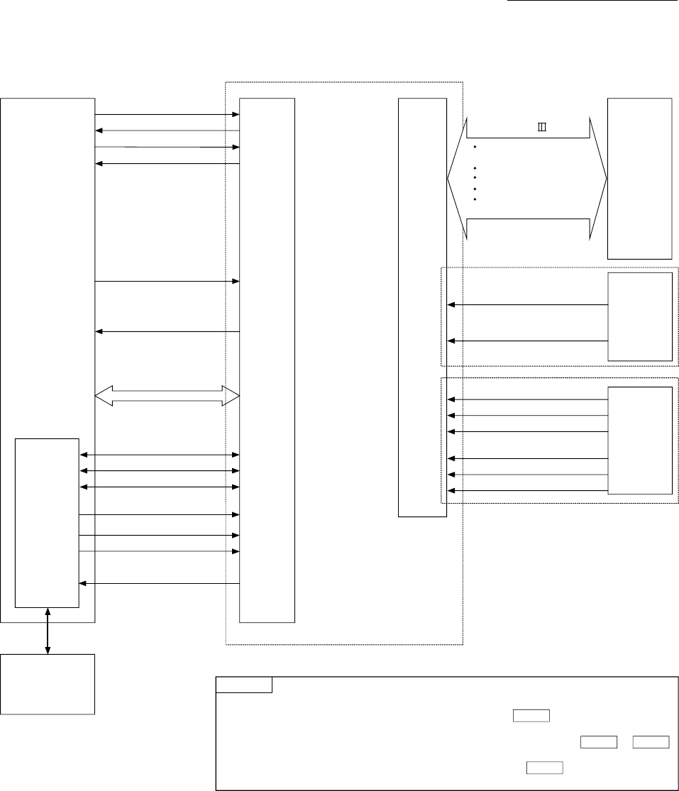
(2) QD77MS16
READY signal
Positioning start signal
BUSY signal
Servo
amplifier
QD77MS16
Y0
Y10 to Y1F
X0
PLC CPU
Manual pulse
generator/
Incremental
synchronous
encoder
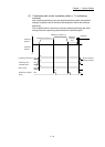
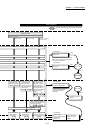
Operation monitor
Parameter write/read
JOG operation, inching operation
(Test)
Positioning operation (Test)
OPR operation (Test)
GX Works2
Peripheral
device
interface
X10 to X1F
Synchronization flag
X1
All axis servo ON signal
Y1
Interface
with
PLC CPU
External
interface
PLC READY signal
Data write/read
Positioning data write/read
Block start data write/read
Operating information of
the servo amplifier
Positioning command
Control command
Servo parameter
External input signal of
the servo amplifier
Manual pulse generator/
Incremental synchronous encoder
A-phase
Manual pulse generator/
Incremental synchronous encoder
B-phase
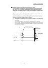
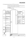
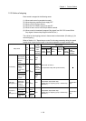
POINT
(1) For QD77MS16, M code ON signal, error detection signal, start complete signal and
positioning complete signal are assigned to the bit of " Status".
(2) For QD77MS16, axis stop signal, forward run JOG start signal, reverse run JOG start
signal, execution prohibition flag are assigned to the buffer memory to .
(3) When using the upper/lower limit signal, stop signal, near-point dog signal of the
external input signal via CPU, use the buffer memory in " External input signal
operation device".
Md.31
Cd.180 Cd.183
Cd.44
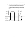
Forced stop input signal
External command signal/
Switching signal
External
input signal
Upper limit signal
Lower limit signal
STOP signal
Near-point dog signal
SSCNET (/H)