


3 - 43
Chapter 3 Specifications and Functions
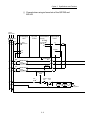
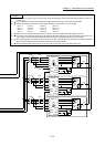
RA2
MC3
4
MCCB4
MC2
4
MCCB3
MC1
4
MCCB2
SSCNET (/H)
2
A
L1
L2
L3
U
W
V
L11
L21
CN1A
CN1B
DICOM
ALM
EM2/1
DOCOM
MR-J4-B
M
U
V
W
Ground
Electro-
magnetic
brake
0
B
L1
L2
L3
U
W
V
L11
L21
CN1A
CN1B
DICOM
ALM
EM2/1
DOCOM
MR-J4-B
M
U
V
W
Ground
Electro-
magnetic
brake
1
C
L1
L2
L3
U
W
V
L11
L21
CN1A
CN1B
DICOM
ALM
EM2/1
DOCOM
MR-J4-B
M
U
V
W
Ground
Electro-
magnetic
brake
24VDC
24VDC
24VDC
3
2
3
2
3
2
RA2
RA2
RA3
RA4
RA5
B
RA3
U
B
RA4
U
B
RA5
U
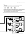
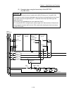
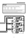
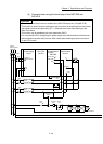
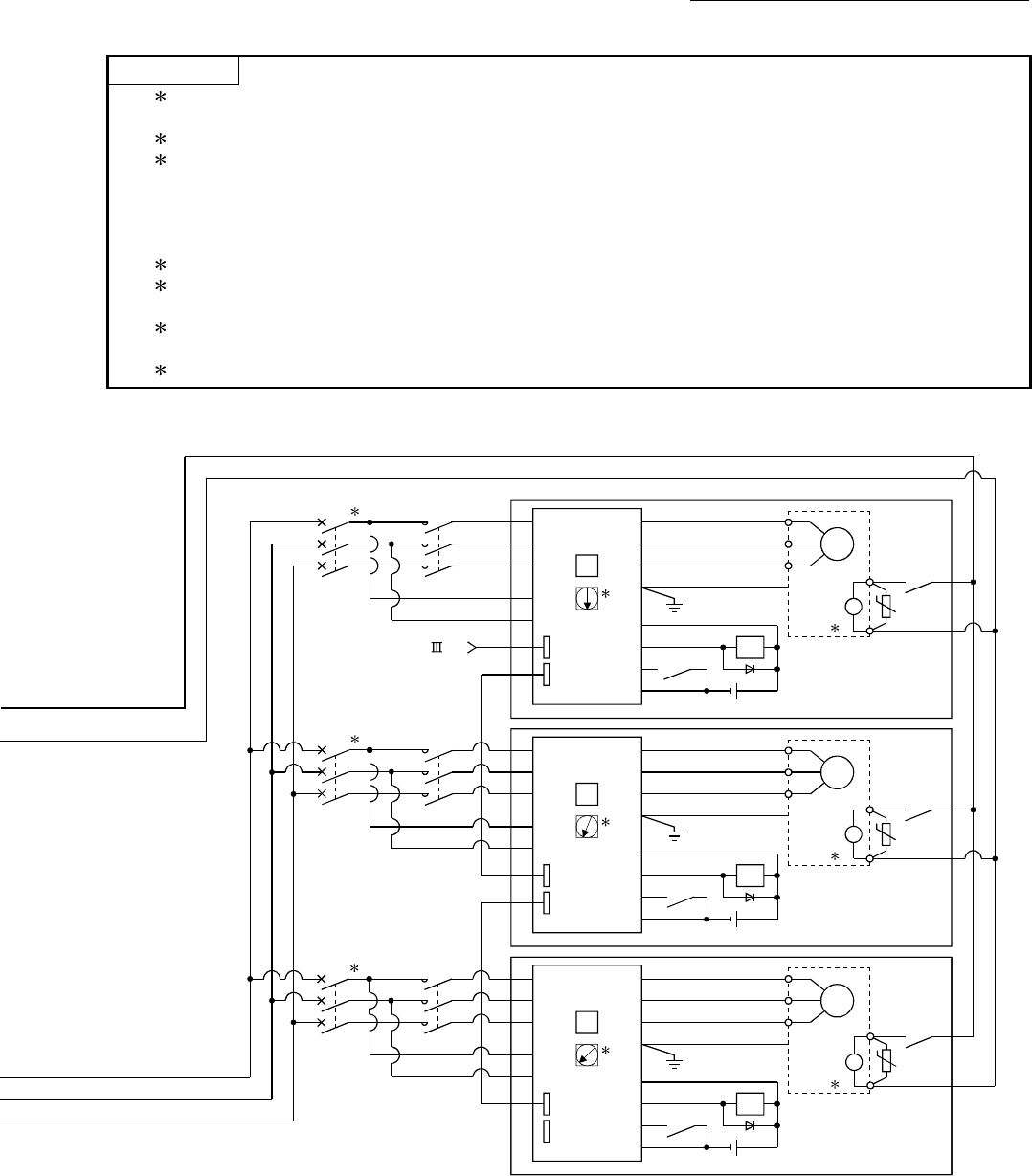
POINT
(1) 1: Configure up the power supply circuit which switch off the electromagnetic contactor (MC) after detection alarm occurrence on
the PLC CPU.
(2)
2: It is also possible to use a full wave rectified power supply as the power supply for the electromagnetic brake.
(3)
3: Set the axis selection rotary switch of servo amplifier as follows to set the axis No. of servo amplifier.
• Axis 1: 0 • Axis 5: 4 • Axis 9: 8 • Axis 13: C
• Axis 2: 1 • Axis 6: 5 • Axis 10: 9 • Axis 14: D
• Axis 3: 2 • Axis 7: 6 • Axis 11: A • Axis 15: E
• Axis 4: 3 • Axis 8: 7 • Axis 12: B • Axis 16: F
(4)
4: Refer to the servo amplifier instruction manual for selection of the circuit breaker and electromagnetic contactor.
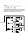
(5)
5: The status of forced stop input signal can be confirmed with "[Md.50] Forced stop input". Be sure that the forced stop 24 V DC
power supply is not used with the electromagnetic brake of the motor or the electromagnetic valve power supply.
(6)
6: The surge suppressor is recommended to be used for an AC relay or electromagnetic contactor (MC) near the servo amplifier.
Refer to the servo amplifier instruction manual for selection of the surge suppressor.
(7)
7: Wire the electromagnetic brake power supply and the control power supply using a separate power supply.