


5 - 34
Chapter 5 Data Used for Positioning Control
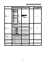
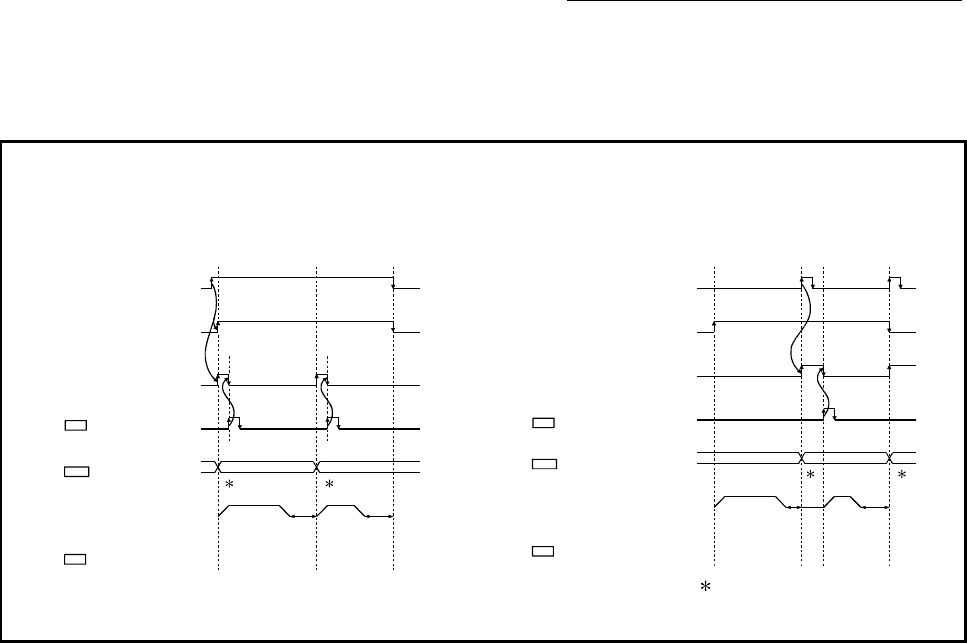
[Pr.18] M code ON signal output timing
This parameter sets the M code ON signal output timing.
Choose either WITH mode or AFTER mode as the M code ON signal output timing.
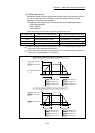
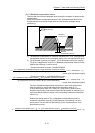
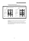
[QD77MS4 operation example]
WITH mode ............ An M code is output and the M code ON signal
is turned ON when a positioning operation
starts.
1
m1 m2
01 (continuous) 00 (end)
Positioning start signal
[Y10, Y11, Y12, Y13]
BUSY signal
[XC, XD, XE, XF]
Positioning
M code ON signal
[X4, X5, X6, X7]
M code OFF request
[1504, 1604, 1704, 1804]
Cd.7
Operation pattern
Da.1
Valid M code
Md.25
1
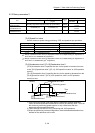
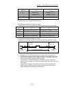
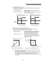
AFTER mode .......... An M code is output and the M code ON signal
is turned ON when a positioning operation
completes.
m1 m2
01 (continuous) 00 (end)
Positioning complete signal
[X14, X15, X16, X17]
BUSY signal
[XC, XD, XE, XF]
Positioning
M code ON signal
[X4, X5, X6, X7]
M code OFF request
[1504, 1604, 1704, 1804]
Cd.7
Operation pattern
Da.1
Valid M code
Md.25
11
1: m1 and m2 indicate set M codes.
(Note): Refer to Section 3.3 for input/output signal of QD77MS16 and Chapter 5 for buffer memory address.
Note: If AFTER mode is used with speed control, an M code will not be output and the M code ON signal will not be turned
ON.
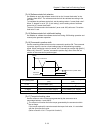
An M code is a number between 0 and 65535 that can be assigned to each positioning
data ([Da.10]).
The sequence program can be coded to read an M code from the buffer memory
address specified by "[Md.25] Valid M code" whenever the M code ON signal turns ON
so that a command for the sub work (e.g. clamping, drilling, or tool change) associated
with the M code can be issued.