


5 - 29
Chapter 5 Data Used for Positioning Control
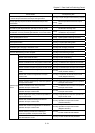
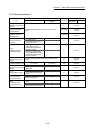
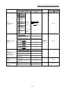
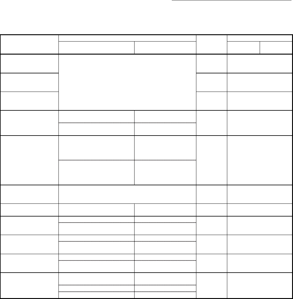
5.2.3 Detailed parameters 1
Item
Setting value, setting range
Default value
Buffer memory address
Value set with GX Works2
Value set with sequence
program
QD77MS2
QD77MS4
QD77MS16
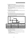
[Pr.11]
Backlash compensation
amount
The setting value range differs according to the "[Pr.1] Unit
setting".
0 17+150n
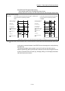
[Pr.12]
Software stroke limit
upper limit value
2147483647
18+150n
19+150n
[Pr.13]
Software stroke limit
lower limit value
–2147483648
20+150n
21+150n
[Pr.14]
Software stroke limit
selection
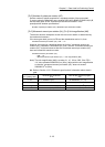
0: Apply software stroke limit on
current feed value
0
0 22+150n
1: Apply software stroke limit on
machine feed value
1
[Pr.15]
Software stroke limit
valid/invalid setting
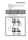
0: Software stroke limit valid during
JOG operation, inching
operation and manual pulse
generator operation
0
0 23+150n
1: Software stroke limit invalid
during JOG operation, inching
operation and manual pulse
generator operation
1
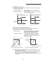
[Pr.16]
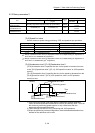
Command in-position
width
The setting value range differs depending on the "[Pr.1] Unit
setting".
100
24+150n
25+150n
[Pr.17]
Torque limit setting value
1 to 1000 (%) 1 to 1000 (%) 300 26+150n
[Pr.18]
M code ON signal output
timing
0: WITH mode 0
0 27+150n
1: After mode 1
[Pr.19]
Speed switching mode
0: Standard speed switching mode 0
0 28+150n
1: Front-loading speed switching
mode
1
[Pr.20]
Interpolation speed
designation method
0: Composite speed 0
0 29+150n
1: Reference axis speed 1
[Pr.21]
Current feed value
during speed control
0: Do not update current feed
value
0
0 30+150n
1: Update current feed value 1
2: Clear current feed value to zero 2
n: Axis No.-1