


6 - 57
Chapter 6 Sequence Program Used for Positioning Control
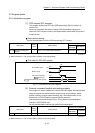
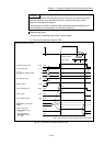
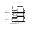
Servo ON conditions
Setting of servo parameter
PLC READY signal [Y0] ON
All axis servo ON [Y1] ON
Starting conditions
To start the control, the following conditions must be satisfied.
The necessary start conditions must be incorporated in the sequence program so
that the control is not started when the conditions are not satisfied.
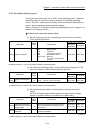
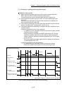
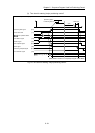
(1) Operation state
Monitor item Operation state
Buffer memory address
QD77MS2
QD77MS4
QD77MS16
[Md.26] Axis operation status "0: Standby" or "1: Stopped" 809+100n 2409+100n
n: Axis No.-1
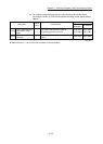
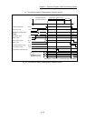
(2) Signal state
Signal name Signal state
Device
QD77MS2
QD77MS4
QD77MS16
Interface
signal
PLC READY signal ON PLC CPU preparation completed Y0
READY signal ON QD77MS preparation completed X0
All axis servo ON ON All axis servo ON Y1
Synchronization flag ON
QD77MS buffer memory
Accessible
X1
Axis stop signal OFF Axis stop signal is OFF Y4 to Y7 [Cd.180] Axis stop
M code ON signal OFF M code ON signal is OFF X4 to X7 [Md.31] Status: b12
Error detection signal OFF There is no error X8 to XB [Md.31] Status: b13
BUSY signal OFF BUSY signal is OFF XC to XF X10 to X1F
Start complete signal OFF Start complete signal is OFF X10 to X13 [Md.31] Status: b14
External
signal
Forced stop input signal ON There is no forced stop input –
Stop signal OFF Stop signal is OFF –
Upper limit (FLS) ON Within limit range –
Lower limit (RLS) ON Within limit range –
: When the synchronous setting of the PLC CPU is made in the nonsynchronous mode, this must be
provided as an interlock.
When it is made in the synchronous mode, no interlock must be provided in the program because the flag is
turned ON when calculation is run on the PLC CPU.