14 - 35
Chapter 14 Common Functions
(4) I/O signals of slave axis
(a) Input signal
[QD77MS2]
Only the error detection signal [X8, X9] is valid. And only the servo error
detection is valid. (The control of slave axis is not influenced even if the
error other than servo error has been occurred.)
[QD77MS4]
Only the error detection signal [X8 to XB] is valid. And only the servo
error detection is valid. (The control of slave axis is not influenced even
if the error other than servo error has been occurred.)
[QD77MS16]
All signals cannot be used. The error detection signal turns ON "Error
detection" ([Md.31]
Status: b13).
(b) Output signal
All output signals of slave axis cannot be used.
(5) Data used for positioning control of slave axis
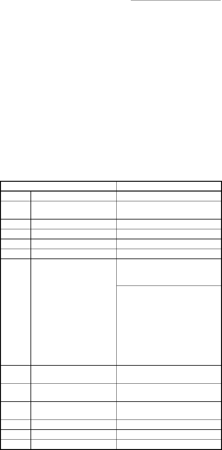
(a) Only the following axis monitor data are valid in slave axis.
Item Remark
[Md.23]
Axis error No. Valid for only servo error detection.
[Md.35]
Torque limit stored value/forward
torque limit stored value
—
[Md.102]
Deviation counter value —
[Md.103]
Motor rotation speed —
[Md.104]
Motor current value —
[Md.107]
Parameter error No. —
[Md.108]
Servo status
The following bit is valid.
• b0: Zero point pass
(Execute OPR to the master axis.)
The following bits are valid.
• b0: READY ON
• b1: Servo ON
• b7: Servo alarm
(Note): The slave axis is always
controlled in torque control mode,
"control mode (high-order buffer
memory address: b2, b3)" is set
to torque control mode (0, 1).
[Md.109]
Regenerative load ratio/Optional
data monitor output 1
—
[Md.110]
Effective load torque/Optional
data monitor output 2
—
[Md.111]
Peak torque ratio/Optional data
monitor output 3
—
[Md.112]
Optional data monitor output 4 —
[Md.114]
Servo alarm —
[Md.120]
Reverse torque limit stored value —


