


59
Virtual Link Trunking (VLT)
Virtual link trunking (VLT) allows physical links between two chassis to appear as a single virtual link to the
network core or other switches such as Edge, Access, or top-of-rack (ToR).
Overview
VLT reduces the role of spanning tree protocols (STPs) by allowing link aggregation group (LAG)
terminations on two separate distribution or core switches and supporting a loop-free topology.
To prevent the initial loop that may occur prior to VLT being established, use a spanning tree protocol.
After VLT is established, you may use rapid spanning tree protocol (RSTP) to prevent loops from forming
with new links that are incorrectly connected and outside the VLT domain.
VLT provides Layer 2 multipathing, creating redundancy through increased bandwidth, enabling multiple
parallel paths between nodes and load-balancing traffic where alternative paths exist.
Virtual link trunking offers the following benefits:
• Allows a single device to use a LAG across two upstream devices.
• Eliminates STP-blocked ports.
• Provides a loop-free topology.
• Uses all available uplink bandwidth.
• Provides fast convergence if either the link or a device fails.
• Optimized forwarding with virtual router redundancy protocol (VRRP).
• Provides link-level resiliency.
• Assures high availability.
CAUTION: Dell Networking does not recommend enabling Stacking and VLT simultaneously. If
you enable both features at the same time, unexpected behavior occurs.
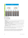
As shown in the following example, VLT presents a single logical Layer 2 domain from the perspective of
attached devices that have a virtual link trunk terminating on separate chassis in the VLT domain.
However, the two VLT chassis are independent Layer2/Layer3 (L2/L3) switches for devices in the
upstream network. L2/L3 control plane protocols and system management features function normally in
VLT mode. Features such as VRRP and Internet Group Management Protocol (IGMP) snooping require
state information coordinating between the two VLT chassis. IGMP and VLT configurations must be
identical on both sides of the trunk to ensure the same behavior on both sides.
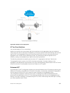
The following example shows how VLT is deployed. The switches appear as a single virtual switch from
the point of view of the switch or server supporting link aggregation control protocol (LACP).
942
Virtual Link Trunking (VLT)