


QoS OUTPUT POLICY mode
exit
5. Enter INTERFACE Configuration mode.
CONFIGURATION mode
interface type slot/port
6. Apply the QoS output policy with the bandwidth percentage for specified priority queues to an
egress interface.
INTERFACE mode
service-policy output output-policy-name
Applying the DCB Policies on Linecard
You can apply DCB policies with PFC and ETS configurations to the linecard on a switch.
To apply DCB policies on linecard, follow this step.
• Apply the DCB map on a linecard.
CONFIGURATION mode
dcb-map {linecard {<0-2>|all} [port-set [<0-3 | all}] backplane all dcb-map-
name
Applying DCB Policies on SFM Ports
To apply DCP configuration on SFM ports, follow these steps.
Configure DCB-MAP on backplane ports in both leaf and spine.
CONFIGURATION Mode
dcb-map sfm all backplane all dcb-map-name
The default is none.
If you apply a DCB Map with PFC disabled (no pfc mode on):
• You can enable link-level flow control on the interface (refer to Using Ethernet Pause Frames). To
delete the input policy, first disable link-level flow control. PFC is then automatically enabled on the
interface because an interface is by default PFC-enabled.
• PFC still allows you to configure lossless queues on a port to ensure no-drop handling of lossless
traffic (refer to Configuring Lossless Queues).
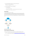
Configure a DCBx Operation
DCB devices use data center bridging exchange protocol (DCBx) to exchange configuration information
with directly connected peers using the link layer discovery protocol (LLDP) protocol.
DCBx can detect the misconfiguration of a peer DCB device, and optionally, configure peer DCB devices
with DCB feature settings to ensure consistent operation in a data center network.
DCBx is a prerequisite for using DCB features, such as priority-based flow control (PFC) and enhanced
traffic selection (ETS), to exchange link-level configurations in a converged Ethernet environment. DCBx
Data Center Bridging (DCB)
259