


The default dot1p priority-queue assignments are applied as follows:
Dell(conf)#do show qos dot1p-queue-mapping
Dot1p Priority : 0 1 2 3 4 5 6 7
Queue : 2 0 1 3 4 5 6 7
Dell(conf)#
NOTE: In Egress queue assignment (8 queues in S6000 and Z9500, 4 against in S5000 and S4810.
PFC is not applied on specific dot1p priorities.
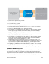
ETS: Equal bandwidth is assigned to each port queue and each dot1p priority in a priority group.
To configure PFC and ETS parameters on an S6000 interface, you must specify the PFC mode, the ETS
bandwidth allocation for a priority group, and the 802.1p priority-to-priority group mapping in a DCB
map. No default PFC and ETS settings are applied to Ethernet interfaces.
Configuring PFC and ETS in a DCB Map
A Z9500 switch supports the use of a DCB map in which you configure priority-based flow control (PFC)
and enhanced transmission selection (ETS) settings. To configure PFC and ETS parameters, you must
apply a DCB map on a Z9500 interface. This functionality is supported on the Z9500 platform.
PFC Configuration Notes
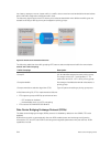
PFC provides flow control based on the 802.1p priorities in a converged Ethernet traffic that is received
on an interface and is enabled by default when you enable DCB. As an enhancement to the existing
Ethernet pause functionality, PFC stops traffic transmission for specified priorities (CoS values) without
impacting other priority classes. Different traffic types are assigned to different priority classes.
When traffic congestion occurs, PFC sends a pause frame to a peer device with the CoS priority values of
the traffic that needs to be stopped. DCBx provides the link-level exchange of PFC parameters between
peer devices. PFC allows network administrators to create zero-loss links for SAN traffic that requires no-
drop service, while at the same time retaining packet-drop congestion management for LAN traffic.
On a Z9500 switch, PFC is enabled by default on Ethernet ports (pfc mode on command). You can
configure PFC parameters using a DCB map or the pfc priority command in Interface configuration
mode. For more information, see Configuring Priority-Based Flow Control.
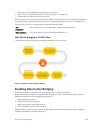
As soon as you apply a DCB map with PFC enabled on an interface, DCBx starts exchanging information
with a peer. The IEEE802.1Qbb, CEE and CIN versions of PFC TLV are supported. DCBx also validates PFC
configurations that are received in TLVs from peer devices. By applying a DCB map with PFC enabled,
you enable PFC operations on ingress port traffic. To achieve complete lossless handling of traffic,
configure PFC priorities on all DCB egress ports.
NOTE: DCB maps are supported only on physical Ethernet interfaces.
• To remove a DCB map, including the PFC configuration it contains, use the no dcb map command
in Interface configuration mode.
• To disable PFC operation on an interface, use the no pfc mode on command in DCB-Map
configuration mode.
Data Center Bridging (DCB)
251