


interconnect links run across 40-Gigabit Ethernet internal ports. A 40-Gigabit Ethernet internal port is
also referred to as a HiGig port.
On the Z9500, each NPU that constitutes a port pipe processes traffic from a set of front-end I/O ports.
In the command-line interface, a Z9500 NPU is entered as unit unit-number.
Configuration Task List for Physical Interfaces
By default, all interfaces are operationally disabled and traffic does not pass through them.
The following section includes information about optional configurations for physical interfaces:
• Overview of Layer Modes
• Configuring Layer 2 (Data Link) Mode
• Configuring Layer 2 (Interface) Mode
• Management Interfaces
• Auto-Negotiation on Ethernet Interfaces
• Clearing Interface Counters
Overview of Layer Modes
On the Dell Networking OS, you can place physical interfaces, port channels, and VLANs in Layer 2 mode
or Layer 3 mode.
By default, VLANs are in Layer 2 mode.
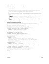
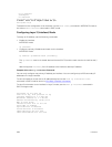
Type of Interface Possible Modes Requires Creation Default State
10–Gigabit Ethernet and
40–Gigabit Ethernet
Layer 2
Layer 3
No Shutdown (disabled)
Management N/A No Shutdown (disabled)
Loopback Layer 3 Yes No shutdown (enabled)
Null interface N/A No Enabled
Port Channel
Layer 2
Layer 3
Yes Shutdown (disabled)
VLAN
Layer 2
Layer 3
Yes, except for the
default VLAN.
No shutdown (active for
Layer 2)
Shutdown (disabled for
Layer 3)
Configuring Layer 2 (Data Link) Mode
Do not configure switching or Layer 2 protocols such as spanning tree protocol (STP) on an interface
unless the interface has been set to Layer 2 mode.
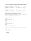
To set Layer 2 data transmissions through an individual interface, use the following command.
• Enable Layer 2 data transmissions through an individual interface.
INTERFACE mode
switchport
402
Interfaces