


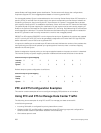
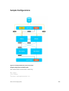
Priority group 1 Assigns traffic to one priority queue with 20% of the link bandwidth and strict-
priority scheduling.
Priority group 2 Assigns traffic to one priority queue with 30% of the link bandwidth.
Priority group 3 Assigns traffic to two priority queues with 50% of the link bandwidth and strict-
priority scheduling.
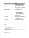
In this example, the configured ETS bandwidth allocation and scheduler behavior is as follows:
Unused
bandwidth
usage:
Normally, if there is no traffic or unused bandwidth for a priority group, the
bandwidth allocated to the group is distributed to the other priority groups
according to the bandwidth percentage allocated to each group. However, when
three priority groups with different bandwidth allocations are used on an interface:
• If priority group 3 has free bandwidth, it is distributed as follows: 20% of the free
bandwidth to priority group 1 and 30% of the free bandwidth to priority group 2.
• If priority group 1 or 2 has free bandwidth, (20 + 30)% of the free bandwidth is
distributed to priority group 3. Priority groups 1 and 2 retain whatever free
bandwidth remains up to the (20+ 30)%.
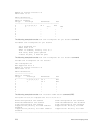
Strict-priority
groups:
If two priority groups have strict-priority scheduling, traffic assigned from the
priority group with the higher priority-queue number is scheduled first. However,
when three priority groups are used and two groups have strict-priority scheduling
(such as groups 1 and 3 in the example), the strict priority group whose traffic is
mapped to one queue takes precedence over the strict priority group whose traffic
is mapped to two queues.
Therefore, in this example, scheduling traffic to priority group 1 (mapped to one strict-priority queue)
takes precedence over scheduling traffic to priority group 3 (mapped to two strict-priority queues).
Priority-Based Flow Control Using Dynamic Buffer
Method
Priority-based flow control using dynamic buffer spaces is supported on the Z9500 platform.
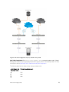
In a data center network, priority-based flow control (PFC) manages large bursts of one traffic type in
multiprotocol links so that it does not affect other traffic types and no frames are lost due to congestion.
When PFC detects congestion on a queue for a specified priority, it sends a pause frame for the 802.1p
priority traffic to the transmitting device.
Pause and Resume of Traffic
The pause message is used by the sending device to inform the receiving device about a congested,
heavily-loaded traffic state that has been identified. When the interface of a sending device transmits a
pause frame, the recipient acknowledges this frame by temporarily halting the transmission of data
packets. The sending device requests the recipient to restart the transmission of data traffic when the
congestion eases and reduces. The time period that is specified in the pause frame defines the duration
for which the flow of data packets is halted. When the time period elapses, the transmission restarts.
Data Center Bridging (DCB)
285