


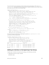

INTERFACE mode or INTERFACE PORT-CHANNEL mode
spanning-tree {0 | mstp | rstp | pvst} rootguard
– 0: enables root guard on an STP-enabled port assigned to instance 0.
– mstp: enables root guard on an MSTP-enabled port.
– rstp: enables root guard on an RSTP-enabled port.
– pvst: enables root guard on a PVST-enabled port.
To disable STP root guard on a port or port-channel interface, use the no spanning-tree 0
rootguard command in an interface configuration mode.
To verify the STP root guard configuration on a port or port-channel interface, use the show spanning-
tree 0 guard [interface interface] command in a global configuration mode.
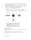
Enabling SNMP Traps for Root Elections and Topology
Changes
To enable SNMP traps individually or collectively, use the following commands.
• Enable SNMP traps for spanning tree state changes.
snmp-server enable traps stp
• Enable SNMP traps for RSTP, MSTP, and PVST+ collectively.
snmp-server enable traps xstp
STP Loop Guard
The STP loop guard feature provides protection against Layer 2 forwarding loops (STP loops) caused by a
hardware failure, such as a cable failure or an interface fault.
When a cable or interface fails, a participating STP link may become unidirectional (STP requires links to
be bidirectional) and an STP port does not receive BPDUs. When an STP blocking port does not receive
BPDUs, it transitions to a Forwarding state. This condition can create a loop in the network.
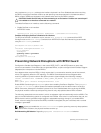
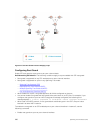
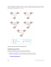
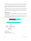
For example, in the following example (STP topology 1, upper left), Switch A is the root switch and Switch
B normally transmits BPDUs to Switch C. The link between Switch C and Switch B is in a Blocking state.
However, if there is a unidirectional link failure (STP topology 1, lower left), Switch C does not receive
BPDUs from Switch B. When the max-age timer expires, the STP port on Switch C becomes unblocked
and transitions to Forwarding state. A loop is created as both Switch A and Switch C transmit traffic to
Switch B.
As shown in the following illustration (STP topology 2, upper right), a loop can also be created if the
forwarding port on Switch B becomes busy and does not forward BPDUs within the configured
forward-delay time. As a result, the blocking port on Switch C transitions to a forwarding state, and
both Switch A and Switch C transmit traffic to Switch B (STP topology 2, lower right).
As shown in STP topology 3 (bottom middle), after you enable loop guard on an STP port or port-channel
on Switch C, if no BPDUs are received and the max-age timer expires, the port transitions from a blocked
state to a Loop-Inconsistent state (instead of to a Forwarding state). Loop guard blocks the STP port so
that no traffic is transmitted and no loop is created.
Spanning Tree Protocol (STP)
881