


VRRP in a VRF Configuration
The following example shows how to enable VRRP operation in a VRF virtualized network for the
following scenarios.
• Multiple VRFs on physical interfaces running VRRP.
• Multiple VRFs on VLAN interfaces running VRRP.
To view a VRRP in a VRF configuration, use the show commands described in Displaying VRRP in a VRF
Configuration.
VRRP in a VRF: Non-VLAN Scenario
The following example shows how to enable VRRP in a non-VLAN.
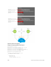
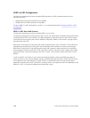
The following example shows a typical use case in which you create three virtualized overlay networks by
configuring three VRFs in two switches. The default gateway to reach the Internet in each VRF is a static
route with the next hop being the virtual IP address configured in VRRP. In this scenario, a single VLAN is
associated with each VRF.
Both Switch-1 and Switch-2 have three VRF instances defined: VRF-1, VRF-2, and VRF-3. Each VRF has a
separate physical interface to a LAN switch and an upstream VPN interface to connect to the Internet.
Both Switch-1 and Switch-2 use VRRP groups on each VRF instance in order that there is one MASTER
and one backup router for each VRF. In VRF-1 and VRF-2, Switch-2 serves as owner-master of the VRRP
group and Switch-1 serves as the backup. On VRF-3, Switch-1 is the owner-master and Switch-2 is the
backup.
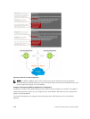
In VRF-1 and VRF-2 on Switch-2, the virtual IP and node IP address, subnet, and VRRP group are the
same. On Switch-1, the virtual IP address, subnet, and VRRP group are the same in VRF-1 and VRF-2, but
the IP address of the node interface is unique. There is no requirement for the virtual IP and node IP
addresses to be the same in VRF-1 and VRF-2; similarly, there is no requirement for the IP addresses to be
different. In VRF-3, the node IP addresses and subnet are unique.
1018
Virtual Router Redundancy Protocol (VRRP)