


percentages in all groups in the DCB map must be 100%. Strict-priority traffic is serviced first.
Afterwards, you can configure either the peak rates or the committed rates. The bandwidth allocated
to other priority groups is made available and allocated according to the specified percentages. If a
priority group does not use its allocated bandwidth, the unused bandwidth is made available to other
priority groups.
• Repeat the above procedure to configure PFC and ETS traffic handling for each priority group
• Specify the dot1p priority-to-priority group mapping for each priority. The priority group range is from
0 to 7. All priorities that map to the same queue must be in the same priority group.
Leave a space between each priority group number. For example: priority-pgid 0 0 0 1 2 4 4 4 in
which priority group 0 maps to dot1p priorities 0, 1, and 2; priority group 1 maps to dot1p priority 3;
priority group 2 maps to dot1p priority 4; priority group 4 maps to dot1p priorities 5, 6, and 7.
Important Points to Remember
• If you remove a dot1p priority-to-priority group mapping from a DCB map (no priority pgid
command), the PFC and ETS parameters revert to their default values on the interfaces on which the
DCB map is applied. By default, PFC is not applied on specific 802.1p priorities; ETS assigns equal
bandwidth to each 802.1p priority.
As a result, PFC and lossless port queues are disabled on 802.1p priorities, and all priorities are
mapped to the same priority queue and equally share the port bandwidth.
• To change the ETS bandwidth allocation configured for a priority group in a DCB map, do not modify
the existing DCB map configuration. Instead, first create a new DCB map with the desired PFC and
ETS settings, and apply the new map to the interfaces to override the previous DCB map settings.
Then, delete the original dot1p priority-priority group mapping.
If you delete the dot1p priority-priority group mapping (no priority pgid command) before you
apply the new DCB map, the default PFC and ETS parameters are applied on the interfaces. This
change may create a DCB mismatch with peer DCB devices and interrupt network operation.
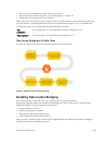
Applying a DCB Map on a Port
When you apply a DCB map with PFC enabled on a switch interface, a memory buffer for PFC-enabled
priority traffic is automatically allocated. The buffer size is allocated according to the number of PFC-
enabled priorities in the assigned map.
To apply a DCB map to an Ethernet port, follow these steps:
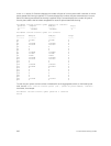
Step Task Command Command Mode
1
Enter interface configuration mode on an
Ethernet port.
interface
{tengigabitEthernet slot/
port |
fortygigabitEthernet
slot/port}
CONFIGURATION
2
Apply the DCB map on the Ethernet port to
configure it with the PFC and ETS settings in
the map; for example:
dcb-map name
INTERFACE
248
Data Center Bridging (DCB)