


packet Dot1p and Dot1p based queue classification. This document will discuss the configurations
required to support PFC for untagged packets based on incoming packet DSCP.
For the tagged packets, Queue is selected based on the incoming Packet Dot1p. When PFC frames for a
specific priority is received from the peer switch, the queue corresponding to that Dot1p is halted from
scheduling on that port, thus honoring the PFC from the peer. If a queue is congested due to packets
with a specific Dot1p and PFC is enabled for that Dot1p, switch will transit out PFC frames for that Dot1p.
The packet Dot1p to Queue mapping for classification on the ingress must be same as the mapping of
Dot1p to the Queue to be halted on the egress used for PFC honoring. Dell Networking OS ensures that
these mappings are identical. This section discusses the Dell Networking OS configurations needed for
above PFC generation and honoring mechanism to work for the untagged packets.
PRIORITY to PG mapping (PRIO2PG) is on the ingress for each port. By default, all priorities are mapped
to PG7. A priority for which PFC has to be generated is assigned to a PG other than PG7 (say PG6) and
buffer watermark is set on PG6 so as to generate PFC.
In ingress, the buffers are accounted at per PG basis and would indicate the number of the packets that
has ingress this port PG but still queued up in egress pipeline. However, there is no direct mapping
between the PG and Queue.
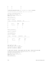
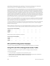
Packet is assigned an internal priority on the ingress pipeline based on the queue to which it is destined.
This Internal-priority to Queue mapping has been modified and enhanced as follows for the device:
Table 15. Priority to Queue Mapping
Internal-
priority
0 1 2 3 4 5 6 7
Queue
2 0 1 3 4 5 6 7
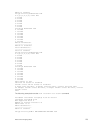
Default dot1p to queue configuration is as follows:
Table 16. Dot1p to Queue Mapping
Packet-
Dot1p
0 1 2 3 4 5 6 7
Queue
2 0 1 3 4 5 6 7
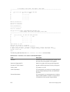
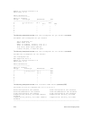
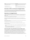
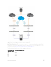
PFC and ETS Configuration Examples
This section contains examples of how to configure and apply DCB policies on an interface.
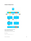
Using PFC and ETS to Manage Data Center Traffic
The following shows examples of using PFC and ETS to manage your data center traffic.
In the following example:
• Incoming SAN traffic is configured for priority-based flow control.
• Outbound LAN, IPC, and SAN traffic is mapped into three ETS priority groups and configured for
enhanced traffic selection (bandwidth allocation and scheduling).
• One lossless queue is used.
282
Data Center Bridging (DCB)