


Networking OS 9.3(0.). Max Use Count mode provides the maximum value of the counters accumulated
over a period of time.
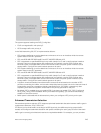
Priority Flow Control (PFC) provides a link level flow control mechanism, which is controlled
independently for each frame priority. The goal of this mechanism is to ensure zero loss under
congestion in DCB networks.
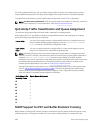
The SNMP support for monitoring PFC and BST counters and statistics is introduced in Dell Networking
OS 9.3(0.1). The enhancement is made on F10-FPSTATS MIB with additional tables to display the PFC and
BST counters and statistics.
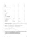
The following new tables are added in F10-FPSTATS MIB in Dell Networking OS 9.3(0.1):
• fpEgrQBuffSnapshotTable
• fpIngPgBuffSnapshotTable
• fpStatsPerPgTable
• pfcPerPrioTable
fpEgrQBuffSna
pshotTable
This table fetches the BST statistics at Egress Port with respect to the buffer used.
This table displays the Snapshot of the Buffer cells used by Unicast and Multicast
Data and Control Queues.
fpIngPgBuffSna
pshotTable
This table fetches the BST statistics at the Ingress Port with respect to the Shared
Cells and the Headroom cells used per Priority Group. The snapshot of the Ingress
Shared cells used and the Ingress Headroom cells used per Priority Group, when
PFC is enabled, will be displayed in this table. This table is indexed by stack-unit
index, port number and the priority group number.
fpStatsPerPgTa
ble
This table fetches the Allocated Min cells, Shared cells and Headroom cells per
Priority Group, the mode in which the buffer cells are allocated - Static or Dynamic
and the Used Min Cells, Shared cells and Headroom cells per Priority Group. The
table fetches a value of 0 if the mode of allocation is Static and a value of 1 if the
mode of allocation is Dynamic. This table is indexed by stack-unit number, port
number and priority group number.
pfcPerPrioTabl
e
This table fetches the number of PFC frames transmitted (PFC Requests) and the
number of PFC frames received (PFC Indications) per priority on a per port basis.
This table is indexed by the stack-unit index, port number and priority.
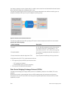
DCB Maps and its Attributes
This topic contains the following sections that describe how to configure a DCB map, apply the
configured DCB map to a port, configure PFC without a DCB map, and configure lossless queues.
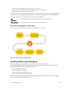
DCB Map: Configuration Procedure
A DCB map consists of PFC and ETS parameters. By default, PFC is not enabled on any 802.1p priority
and ETS allocates equal bandwidth to each priority. To configure user-defined PFC and ETS settings, you
must create a DCB map. The following is an overview of the steps involved in configuring DCB.
• Enter global configuration mode to create a DCB map or edit PFC and ETS settings.
• Configure the PFC setting (on or off) and the ETS bandwidth percentage allocated to traffic in each
priority group, or whether the priority group traffic should be handled with strict priority scheduling.
You can enable PFC on a maximum of two priority queues on an interface. Enabling PFC for dot1p
priorities makes the corresponding port queue lossless. The sum of all allocated bandwidth
Data Center Bridging (DCB)
247