Chapter 6 LightField and Gated Operation 97
6.3 Timing Mode
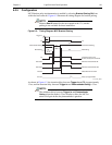
In Gate Mode, the internal timing generator uses Internal Sync timing which initiates a
readout cycle following each internally-generated timing pulse sequence.
1
Internal handshakes are used to prevent:
• A readout from being initiated when the timing generator is busy;
• Biasing the photocathode ON while a readout cycle is in progress.
The following camera parameters are automatically configured by WinX and cannot be
changed:
• Exposure Time: Set to 0;
• Continuous Cleans: disabled;
• Shutter Control: Disabled Opened.
NOTE:
These parameters may not be visible in some versions of the
application software.
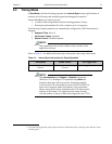
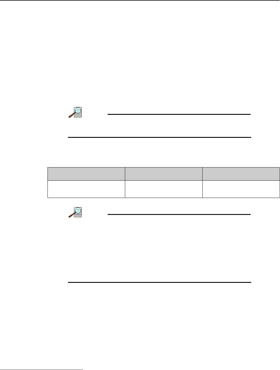
Refer to Table 6-1 for additional Internal Sync information when using Gated mode.
NOTE:
The Accumulations and Images (or Spectra) parameters
(WinView/32 or WinSpec/32 Acquisition Setup
Main tab)
determine how data will be processed. Integrating multiple
events on the CCD really brings the power of the PI-MAX4 to
bear on low-light gate-mode experiments. If the experiment
allows, many pulses can be summed on the CCD with no pulse
artifacts in the readout. The signal increases nearly linearly
with the number of pulses (within limits imposed by the CCD.)
1. An internal timing generator pulse sequence consists of a Gate Start pulse, a Gate Stop pulse, and one or more
Auxiliary pulses.
Table 6-1: Internal Sync Information for Gated Operation
Timing Mode Shutter Control Ext. Trigger Input
Controlled by Internal Timing
Generator
Controlled by Internal Timing
Generator
Trigger In BNC


