Chapter 16 Component Descriptions 239
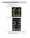
16.2.1 AUX I/O
This is a 26-pin female DB connector. The standard AUX I/O cable included with all PI-MAX4
systems, provides easy access to five (5) I/O signals which can be used to input a trigger to
initiate data acquisition, monitor frame readout status, and/or control an external shutter.
The five I/O signals are:
• T0 Out;
• Pre-Trigger In;
• SyncMASTER1;
• General Purpose Input 0;
• SyncMASTER2.
Refer to Section A.6, AUX I/O Interface, on page 258 for complete information about the
AUX I/O interface.
16.2.2 AUX Out
This is a standard female BNC connector.
The AUX Out signal is a DC-coupled programmable delay trigger output (T0) used to
synchronize external devices with PI-MAX4. The host software sets the Delay Time for this
output with respect to the internal timing generator trigger time.
The delay is programmable from 0.01 ns to 1 second.
The source impedance is approximately 100 and it will provide > 1 V into 50 .
16.2.3 AUX Power [PI-MAX4: 1024i-RF only]
Power input for the RF modulation section of a PI-MAX4: 1024i-RF camera.
16.2.4 Coolant Ports
Two standard ¼-inch barbed brass fittings for circulating coolant are located on the back
panel. Either port may be used as the inlet.
CAUTION!
!
The coolant cannot be chilled.
Use Princeton Instruments’ CoolCUBE
II
coolant circulator.
REFERENCES:
For additional information, refer to:
• Section 3.7, Connect the Circulator [Liquid-Cooled
Cameras Only], on page 42;
• Section 5.5, Temperature Control, on page 66.
NOTE:
Although circulating water will extend the camera’s cooling
capabilities, it is not necessary. Most of the camera’s cooling is
provided by the fan.


