Chapter 14 PI-MAX4: EM Family 221
14.2.8 Configuring a Kinetics Experiment
This procedure assumes:
• The system has already been setup per instructions in previous chapters.
• Previous sections of this chapter have been read and are understood.
• Familiarity with the application software.
• The system is being operated in imaging mode.
• The target is a sharp image, text, or drawing that can be used to verify that the
camera is “seeing” and can be used to maximize focus.
• A portion of the CCD is being illuminated as illustrated in Figure 14-9.
• LightField is the application software being used.
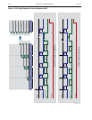
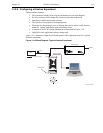
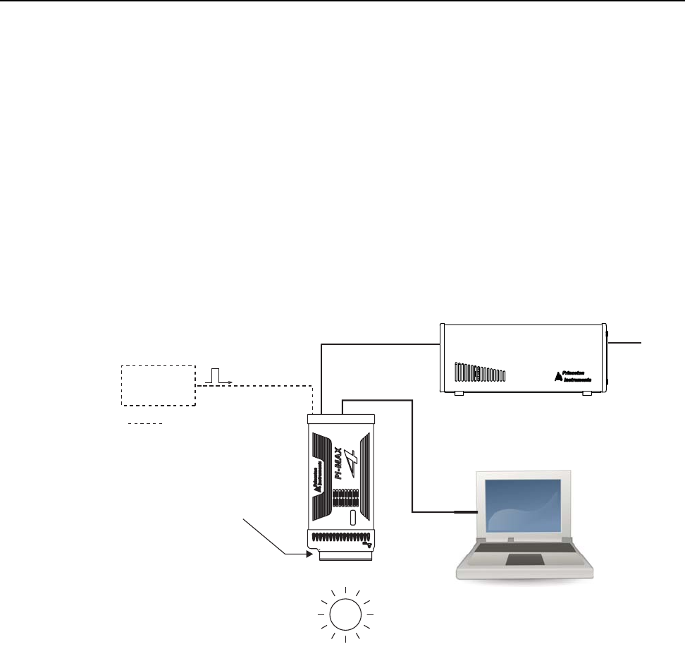
Figure 14-16 illustrates a high-level block diagram of the equipment setup for a typical
Kinetics experiment.
Figure 14-16:Block Diagram: Typical Kinetics Experiment
Trigger Source
(TTL)
Trigger In
External
Trigger
Ethernet Cable
Power Supply
100/240
Masked Array
For Triggered Acqusition
4411-0137_0132


