Chapter 5 Gate Mode Operation 77
5.8.3.1 CCD Type and Readout Port(s)
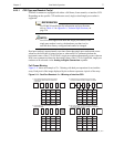
PI-MAX4 cameras are equipped with either a full frame, frame transfer, or interline CCD.
Depending on the specific CCD architecture used, single or dual/single port readout is
supported.
REFERENCES:
For PI-MAX4 model-specific information and specifications,
refer to Table A-3 in Appendix A, Technical Specifications, on
page 256.
NOTE:
For CCDs that support both dual and single port readout, when
single port readout is active, the hardware port that is to be
used has been factory-configured and cannot be changed.
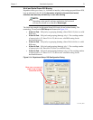
Dual port readout is approximately two times faster than single port readout and occurs
whenever the full frame is being read out or when an ROI is symmetrical about the
horizontal center of the CCD. In WinX, single port readout automatically occurs when an
ROI is not symmetrical about the horizontal center of the CCD. In LightField, single port
readout can be selected via the
Analog to Digital Conversion expander.
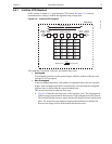
Full Frame Binning
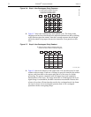
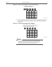
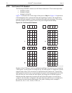
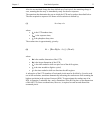
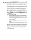
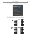
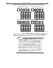
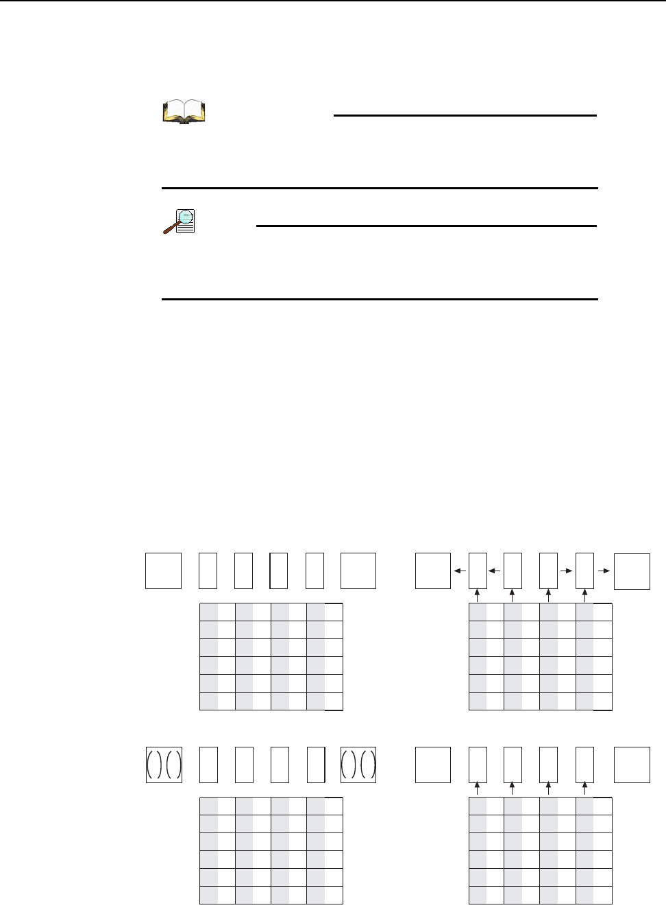
Figure 5-11 shows an example of 2 x 2 binning with dual port operation for an interline
array. Each pixel of the image displayed by the software represents 4 pixels of the array.
Figure 5-11: Dual Port Readout: 2 × 2 Binning of Interline CCD
Empty Readout Register. Exposure has ended
and image has been shifted to masked area
of each pixel.
.
Charges from two masked areas in each column
have been shifted to Readout Register and added.
After sum of first four charges have been transferred
from Output Nodes, next set of charges are shifted into
Readout Register and added.
Four charges have been shifted to the Output
Nodes and added.
A1 B1 C1
A2 B2
A4
A3
B4
B3
A6
A5
B6
B5
C2
C4
C3
C6
C5
D1
D2
D4
D3
D6
D5
A4
A3
B4
B3
A6
A5
B6
B5
C4
C3
C6
C5
D4
D3
D
6
D5
A1
A2
+
B1
B2
+
+
A6
A5
B6
B5
C6
C5
D6
D5
A4
A3
B4
B3
A6
A5
B6
B5
C4
C3
C6
C5
D4
D3
D
6
D5
A1
A2
+
C1
C2
+
D1
D2
+
B1
B2
+
1
43
2
C1
C2
+
D1
D2
+
+
A3
A4
+
C3
C4
+
D3
D4
+
B3
B4
+
4411-0137_0031


