158 PI-MAX
®
4 System Manual Issue 4
9.5 Configure a Dual Trigger DIF Experiment
This section describes the configuration of a dual trigger DIF experiment.
9.5.1 Hardware
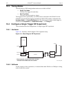
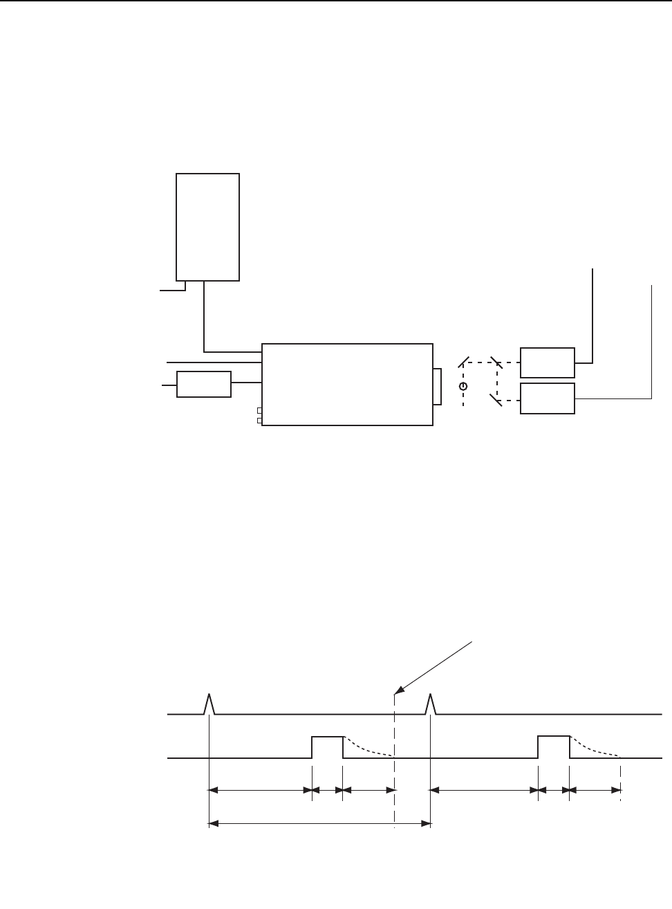
Figure 9-7 illustrates a block diagram of the equipment setup.
Figure 9-7: Block Diagram: DIF Experiment
9.5.2 Software Setup and Operation
The operation of the PI-MAX4 in DIF mode is similar to the standard operation of a
PI-MAX4 with SuperSYNCHRO. There are only a few differences due to the special timing
modes of DIF, and they will be outlined here.
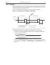
Figure 9-8 illustrates the timing diagram for a single trigger DIF experiment.
Figure 9-8: Timing Diagram: DIF Operation, Dual Trigger
LASER 1
LASER 2
Trigger 1
Trigger 2
100-240
100-240
GiGE
Trigger In
Power
Supply
PI-MAX4
Computer
4411-0137_0090
* SPECTROGRAPH, COOLANT CIRCULATOR, AND DRY
NITROGEN
TANK CONNECTIONS ARE OPTIONAL
' ,QLWLDO*DWH'HOD\XV ' 3XOVH*DWH'HOD\PLQGHOD\RIFDPHUDaQV
3' 3KRVSKRU'HFD\7LPH
W1 3XOVH*DWH:LGWK
: 3XOVH*DWH:LGWK
D1 W1 D2 W2PD PD
75,**(5
,0$*(6
FIRST FRAME SECOND FRAME
6+,)7%(+,1'
0$6.
77 7LPHEHWZHHQ7ULJJHUV'Z3'
77
4411-0137_0097


