180 PI-MAX
®
4 System Manual Issue 4
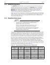
12.3 MONITOR Operation
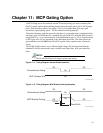
The MONITOR output at the BNC on the rear panel may be used with an oscilloscope to
determine when the intensifier is being gated on. The
MONITOR output is calibrated to
provide a rising edge at the time the optical gate is opening (±500 ps.) The start of the
MONITOR pulse coincides with the opening of the intensifier, but the width of the
MONITOR pulse is unrelated to the total intensifier ON time. Refer to Section 5.6.1.1,
Exposure Timing, on page 68 for additional information.
Many users do not have oscilloscopes available that can reliably capture picoseconds pulse
widths. Therefore, a pulse width of ~6 ns is used independent of the configured gate width.
The true optical gate width is shown in the application software and is calibrated at the
factory using a fast pulsed laser.
12.4 Repetition Rate Issues
NOTE:
New, sub-nanosecond gate generators are capable of sustaining
repetition rates of 100 kHz and therefore the information
included in this section is not relevant.
However, when using an older gate generator device, the
information included in this section must be considered.
Refer to the manufacturer-supplied technical specifications for
the gate generator being used to determine if it is capable of
sustaining 100 kHz repetition rates.
The picosecond gate generator operates at high peak power levels and therefore has a lower
repetition rate capability than the main gate generator. The normal peak repetition rate for
the picosecond gate generator is 100 kHz. However, it will allow 2 gates to be generated at
up to 1 MHz to allow for DIF operation. In addition, the 100 kHz repetition rate cannot be
sustained continuously. Practically, it must be interrupted periodically to read the CCD so
this is not as great a problem as it may seem. The picosecond gate generator includes a
digital average duty factor limiting circuit that will lock out gating (and light the red LED
on the rear panel) to limit the average heat buildup in the gating circuit. This allows
continuous operation at 10 kHz, and varying numbers of gates per frame at higher rates,
depending on the read out time. Acquisitions of a few frames can usually be done with more
gates per frame without hitting the limit and red light. Some typical numbers for sustained
operation with a PI-MAX4:1024i are provided in Table 12-1.
Table 12-1: Typical Picosecond Gating Information: PI-MAX4:1024i
Repetition Rate
(kHz)
ADC Rate
(MHz)
Binning and ROI
Readout Time
(ms)
Gates/Frame
90 16 Full frame ~40 450
75 16 Full frame ~40 461
50 16 Full frame ~40 500
50 16 1Hx100V ROI ~3.4 145
25 16 Full frame ~40 666
10 any any No limit


