Chapter 5 Gate Mode Operation 81
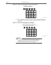
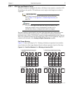
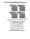
Figure 5-16: Single Port Readout: Partial Frame, 2×2 Binning, Interline CCD
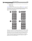
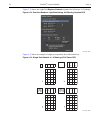
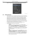
Figure 5-17 shows the LightField Region of Interest expander and 5 x 3 binning setup for
an interline sensor with dual port readout selected. Both the
Full Sensor, Binned and the
Custom Region(s) of Interest results of using the 5 and 3 bin values are reported.
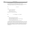
NOTE:
On LightField’s Region of Interest expander, you can select
Full Sensor, Binned and enter Bin W and Bin H values that
would not be allowed if you selected
Custom Region(s)
Interest
and entered them in the Edit Regions of Interest
window. For example a Bin W=5 and a Bin H=3 would not be
allowed via the
Edit Regions of Interest window until you
created a horizontally centered ROI whose dimensions would
permit even division by those values. If you use the
Full
Sensor, Binned
function, LightField creates the appropriately
sized ROI and reports the resulting image size. The
Custom
Region(s) of Interest
panel shows the non-binned ROI size
and the bin values that will be applied to it.
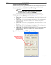
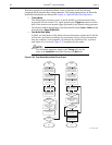
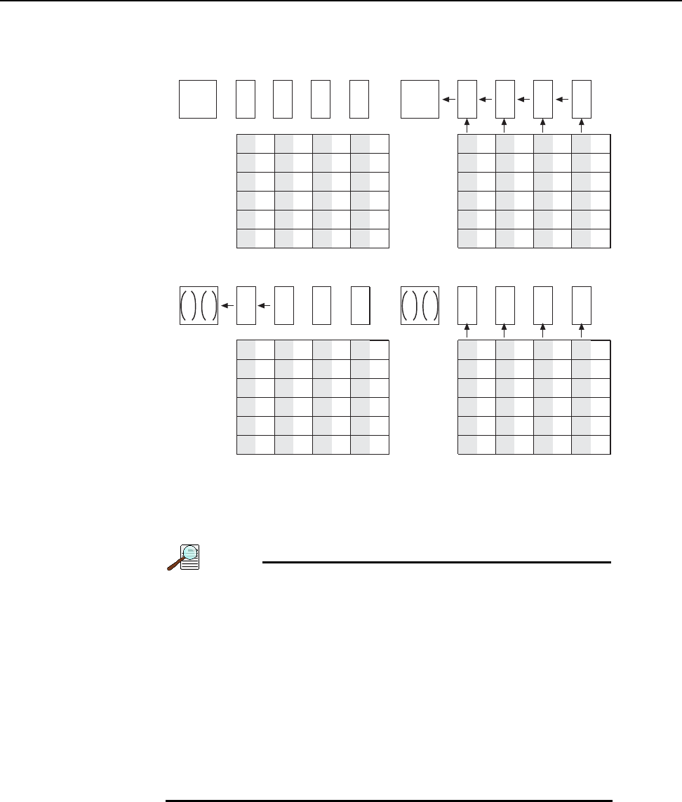
Empty Readout Register. Exposure has ended
and image has been shifted to masked area
of each pixel.
.
Charges from two masked areas in each column have
been shifted to Readout Register and added.
After sum of first four charges have been transferred
from Output Node, next four charges are shifted into
Output Node and added.
Four charges have been shifted to the Output
Node and added.
A1 B1 C1
A2 B2
A4
A3
B4
B3
A6
A5
B6
B5
C2
C4
C3
C
6
C5
D1
D2
D4
D3
D
6
D5
A4
A3
B4
B3
A6
A5
B6
B5
C4
C3
C
6
C5
D4
D3
D
6
D5
C1
C2
+
D1
D2
+
A1
A2
+
B1
B2
+
+
A4
A3
B4
B3
A6
A5
B6
B5
C4
C3
C
6
C5
D4
D3
D
6
D5
C1
C2
+
D1
D2
+
+
A4
A3
B4
B3
A6
A5
B6
B5
C4
C3
C
6
C5
D4
D3
D
6
D5
A1
A2
+
C1
C2
+
D1
D2
+
B1
B2
+
12
43
4411-0137_0036


