Chapter 1 Introduction 21
1.2 Summary of PI-MAX4 Data Acquisition
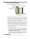
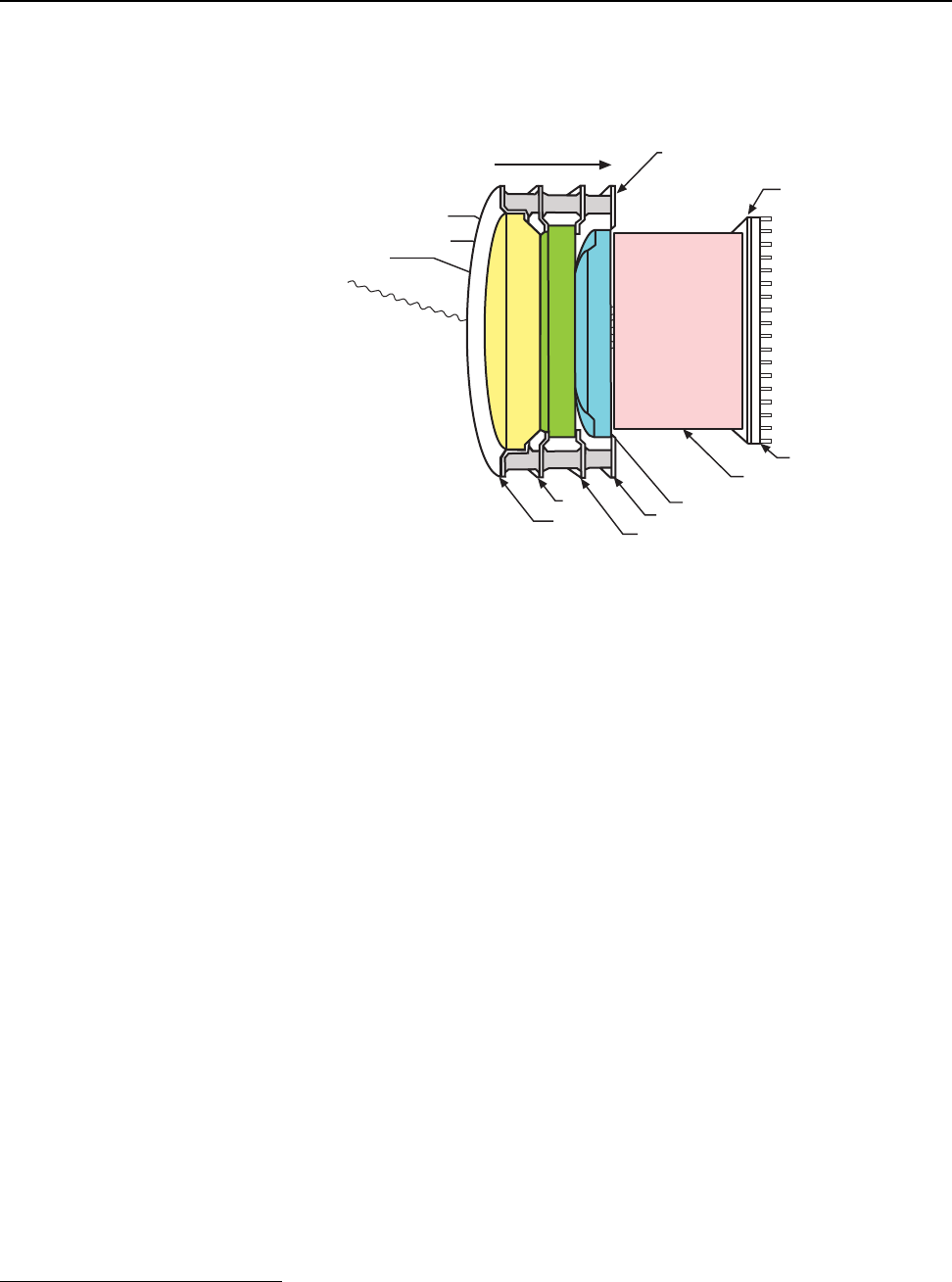
Figure 1-2 illustrates the major components that comprise an Intensifier-CCD.
Figure 1-2: Major Components of the Intensifier-CCD
In the PI-MAX4 camera, the input image is focused onto the photocathode of an image
intensifier tube. The tube electronically amplifies the image and outputs it, much brighter, as
gray-scaled green light. That light is then coupled to the CCD using a fused fiber-optic bundle
from the output of the image intensifier to the front side of the CCD. The image at the output
of the image intensifier is translated to the input of the CCD at the same size.
1
After being
detected by the CCD, the image is read out to the internal controller, where it is digitized, and
then transferred to the computer for processing via a high-speed data link.
The sequence below steps through the process by which photons are converted to data that
can be displayed on a computer monitor. For the sake of simplicity, triggers and gate pulses
are not mentioned and it is assumed that a high speed (GigE) serial interface card is installed
in the host computer. When reading through the sequence, keep in mind that electrons are
attracted to more positively charged surfaces and are repelled by more negatively charged
surfaces. This principal is used to control electron flow through the intensifier tube:
changing the photocathode voltage with respect to the voltage at the MCP input is used to
switch (gate) the intensifier on and off.
1. Incident photons pass through the intensifier input window, strike the photocathode, and
release electrons. See Figure 1-2.
2. Assuming that the intensifier is gated ON (the photocathode is more negative than the
MCP input,) these electrons will be attracted to the MCP input.
Gating acts like a
shutter in that gating the intensifier on allows the CCD to see light and gating the
intensifier off prevents the CCD from seeing light.
3.
Since the voltage at the MCP output is much more positive, most of the electrons
accelerate into the MCP channels and, if they hit the channel walls, will generate
additional electrons, resulting in electron gain.
The amount of gain is adjusted by
increasing or decreasing the voltage at the MCP output.
1. Units having a tapered fiber optic bundle may also be available. Contact the factory for information.
Electr
Intensifier Gated On
Input Window
CCD Array
Fiberoptic Bundle
on Flow
Input Window
-200 V
0 V
600 V - 900 V
6 kV
Electrical Connection Rings
Photocathode
Microchannel Plate (MCP)
: - +
Incident Light
Phosphor (Fluorescent Screen)
4411-0137_0001


