Chapter 10 WinX and Dual Image Feature 163
10.4.3 Operation
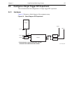
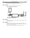
The operation of the PI-MAX4 in DIF mode is similar to standard operation of a PI-MAX4
with SuperSYNCHRO. This section describes the minor operational differences that are due
to the special timing modes required for DIF.
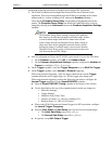
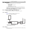
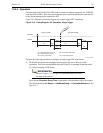
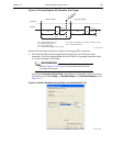
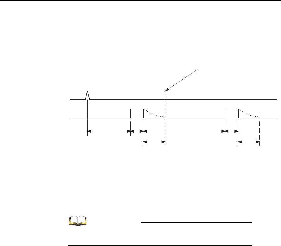
Figure 10-2 illustrates the timing diagram for a single trigger DIF experiment.
Figure 10-2: Timing Diagram: DIF Operation, Single Trigger
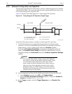
Perform the following procedure to configure a single trigger DIF experiment:
1. The PI-MAX4 camera must be aligned and focused on the area of interest for this
experiment. This is best accomplished while the PI-MAX4 is operating in Interline mode
(i.e., before switching to DIF mode.)
REFERENCES:
Refer to Chapter 4, First Light, for information about the initial
focusing of the camera.
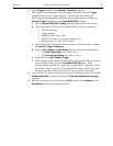
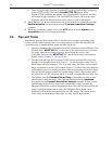
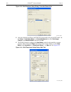
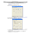
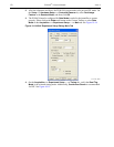
Verify that the
Phosphor Decay Time is appropriate to the phosphor used by the camera.
This field is located on the
Setup —> Hardware Setup —> Controller/Camera tab. See
Figure 10-3.
' ,QLWLDO*DWH'HOD\XV ' ,QWHU3XOVH*DWH'HOD\
3' 3KRVSKRU'HFD\7LPH
: 3XOVH*DWH:LGWK : 3XOVH*DWH:LGWK
D1 W1 D2 W2
PD PD
75,**(5
,0$*(6
FIRST FRAME SECOND FRAME
6+,)7%(+,1'
0$6.
4411-0137_0091


