147
Chapter 8: Timing Generator
This chapter describes the internal timing generator for the PI-MAX4.
8.1 Pulse Set
A Pulse Set comprises the following signals:
• MCP_GATE;
• START;
• STOP;
• AUX1;
• SyncMASTER.
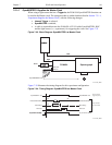
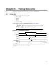
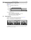
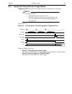
START and STOP define the photocathode gate pulse. See Figure 8-1.
NOTE:
MCP GATE, START, and STOP are not visible to the user and
are included for informational purposes only.
Figure 8-1: Timing Diagram: Pulse Set
The EXPOSE signal remains high for the duration of the pulse set and goes low upon
approximately 15 ns after pulse completion.
MCP_GATE
START
STOP
AUX1
SyncMASTER
(AUX2)
4411-0137_0086


