Chapter 13 PI-MAX4: 1024i-RF and RF Modulation 201
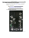
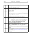
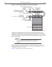
Table 13-2: PI-MAX4: 1024i-RF Connectors, Indicators, and Switches (Sheet 1 of 2)
# Label Description
1 MON RF OUT Provides an approximate indicator of the user-defined RF applied to the photocathode.
2 MONITOR Provides an output for TTL logic 1 pulse delayed ± 3 ns with respect to photocathode gating. Cable delay,
~1.5 ns/ft, will be in addition to the delay at the connector.
3 AUX OUT DC-coupled variable delay trigger output for synchronizing other system components with the
PI-MAX4: 1024i-RF internal timing generator. The host software sets the Delay Time of this output with
respect to the internal timing generator trigger time. The source impedance is approximately 100 and it
will provide > 1 V into 50 .
4 GIG-E Gigabit Ethernet connector.
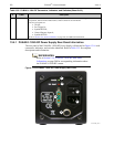
5 POWER 7-pin D specialty connector; connects to the PI-MAX4: 1024i-RF power supply. See Figure 13-15.
6 LOGIC OUT 0 to +3.3V logic level output (TTL-compatible.) WinX software-selectable Acquiring, Image Shift,
Logic 1, Read Out, Shutter, and Wait for Trigger signal. When the Invert LOGIC check box is checked,
the output is at a logic low when the action is occurring.
7 AUX POWER Power input for the RF modulation section of the camera.
8 USER RF OUT User-programmable continuous frequency output to synchronize external devices with
PI-MAX4: 1024i-RF. When used, must be connected to a 50 load (standard for RF.)
9 I.I.T. PWR This switch biases the image intensifier photocathode ON or OFF. When the I.I.T. switch is set to ON,
the photocathode can be gated ON.
NOTE: In WinX, selecting SAFE on the Experiment Setup —> Main dialog overrides
control and prevents the photocathode from being biased on regardless of the I.I.T.
switch setting. In LightField, this override is done by unchecking the
Enable
Intensifier
check box on the Common Acquisition Settings expander.
When the I.I.T. switch is set to OFF, the photocathode cannot be turned on from software.
It is advisable to turn the I.I.T. switch to its OFF position as a fail-safe measure if the
PI-MAX4: 1024i-RF remains ON but unused for a period of time.
10 TRIGGER IN When external triggering is selected in the software, the internal timing generator will be triggered by an
externally derived trigger pulse (range of ±5.5 V) applied to this input. The threshold, slope, coupling
mode (i.e., AC or DC,) and input impedance (i.e., High or 50 W,) are selectable in software. The
associated Green LED flashes each time PI-MAX4: 1024i-RF is triggered (glows steadily at high
repetition rates.)
In gated operation, the green LED indicator flashes each time the PI-MAX4: 1024i-RF is triggered. The
actual triggering can also be readily determined by observing the signal at the Monitor output with a fast
oscilloscope.
11 IN and OUT Standard ¼-inch barbed brass fitting for circulating coolant located on the back panel. Either port may be
used as the inlet. The coolant must not be chilled. Use the Princeton Instruments CoolCUBE
II
coolant circulator. Refer to Section 3.7, Connect the Circulator [Liquid-Cooled Cameras Only], on
page 42, for complete information.
12 READY OUT The output level at this BNC is normally LOW. It changes state on completion of cleaning cycles before
the first exposure


