Appendix A Technical Specifications 259
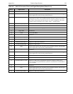
5 — Not Used
6 GND System chassis ground. Any external circuitry intended to interface with the trigger
control signals must reference this ground connection.
7 SyncMASTER1 Output LVCMOS Active high. User-configurable output. SyncMASTER1 can be user-
configured to provide a user-specified continuous frequency output (not just when
the camera is taking data) until halted by the user. In this configuration, the output
could be used to synchronize a laser, shutter, AOTF… with the camera.
8 General Purpose Input 0 Reserved for future use as general LVCMOS input limited ESD protection.
9 L_Shutter (via 1 k) Do Not Use.
10 Source Comp Reserved for future Use. Analog Input.
11 Logic GND Do Not Use.
12 +5.9 V +5.9 V thru 100
13 — Not Used
14 General Purpose Output 3 Requires a 1 k resistor. Reserved
15 General Purpose Output 2 Requires a 1 k resistor. Reserved
16 General Purpose Output 1 Requires a 1 k resistor. Reserved
17 SyncMASTER2 Output Requires a 1 k resistor.
18 GND System chassis ground. Any external circuitry intended to interface with the trigger
control signals must reference this ground connection.
19 — Not Used
20 GND System chassis ground. Any external circuitry intended to interface with the trigger
control signals must reference this ground connection.
21 General Purpose Input 2 Requires a 1 k resistor. Reserved
22 General Purpose Input 1 Requires a 1 k resistor. Reserved
23 SyncMASTER2 (via 10 ) Requires a 10 resistor. Programmable continuous frequency output (100 ns -
6.55 ms delay from SyncMASTER1) synchronize external devices with PI-MAX4
(e.g. Q-switch.)
24 — Not Used
25 GND System chassis ground. Any external circuitry intended to interface with the trigger
control signals must reference this ground connection.
26 General Purpose Input 3 Requires a 1 k resistor. Reserved
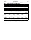
Table A-6: AUX I/O Connector Pinout and Signal Descriptions (Sheet 2 of 2)
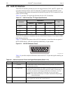
Pin # Signal Name Description


