Chapter 11 MCP Gating Option 177
11.2 Gain Variation
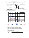
MCP gain approximately doubles for each 50 V increase in voltage. Therefore, small
ripples in the MCP voltage as a result of the gating waveform will cause gain changes that
vary with time after the rising edge of the gate pulse. A gain overshoot of 20% to 30%
during the first 20 ns of a gate pulse is typical, with smaller variations later in time if a wider
gate pulse is used. For a given gain setting and pulse width, these variations are reasonably
repeatable, and may be calibrated.
11.3 Fluorescence Experiment
A typical laser-induced fluorescence experiment might incorporate a pulsed laser that
excites a sample with the laser beam and that additionally provides a trigger to the
PI-MAX4. When the laser pulse hits the sample, some atoms are raised to a higher energy
state and then spontaneously relax to the ground state, emitting photons as they do to
generate the fluorescence signal. This signal can be applied to a spectrograph that spreads
the fluorescence spectrum across the photocathode of the PI-MAX4. The spectrum would
then be intensified and applied to the PI-MAX4’s CCD array.
11.4 Cabling for MCP Gated Operation
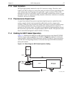
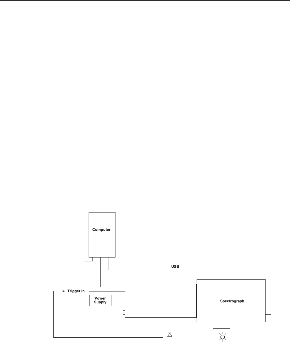
Figure 11-5 illustrates the cabling for an MCP gated experiment using SuperSYNCHRO.
The laser trigger output is applied to the PI-MAX4’s
Trigger In connector to initiate the
timing sequence. SuperSYNCHRO outputs gate the MCP on and off. To prevent artifacts
from the laser from degrading the data, it is essential that SuperSYNCHRO be inhibited
during each readout.
Figure 11-5: Block Diagram: MCP Gated Operation Cabling
PI-MAX4
Photodiode
GigE
100/240
100/240
100/240
4411-0137_0108


