68 PI-MAX
®
4 System Manual Issue 4
5.6 Exposure
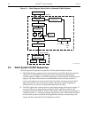
Data acquisition has two parts: exposure and readout. Exposure refers to the integration of a
signal of interest on the CCD array and readout is the transfer of the integrated signal from
the array pixels to a shift register and from there to a preamplifier. During exposure, each
pixel in the two-dimensional grid of individual pixels senses the intensity of light falling on
its collection area and stores a proportional amount of charge in its associated well. Once
charge accumulates for the exposure time (via gating sequences defined in the application
software,) the pixels are read out serially.
CCD arrays are always sensitive to light. Therefore, with very few exception, light must not
be allowed to fall on the array during readout. Intensified cameras such as the PI-MAX4
rely on gating the intensifier off to prevent light from reaching the array. During each data
acquisition, the intensifier is gated on and off (this may happen a number of times if there
are multiple gates per exposure) to allow the pixels to register light during the “on” period.
It is gated off for the readout period.
5.6.1 Exposure with an Image Intensifier
PI-MAX4 cameras use an image intensifier both to gate light on and off and to greatly
increase the brightness of the image. In these cameras the image intensifier detects and
amplifies the light, and the CCD is used for readout. The exposure programmed by software
in this case refers to duration of gating of the intensifier.
The intensifier’s Micro-Channel Plate (MCP) is composed of more than 10
6
individual
miniature electron multipliers with excellent input-to-output spatial geometric accuracy.
Intensifier gain is varied by adjusting the voltage across the MCP or the voltage across the
MCP output and the phosphor. This second parameter is a factory adjustment as it affects
both the gain and the resolution of the intensifier.
Detection of extremely weak Continuous Wave (CW) signals (e.g., luminescence, Raman
scattering from solid state samples,) is typically limited by the dark current of the
intensifier's photocathode, typically referred to as the Equivalent Background Illumination
(EBI.)
5.6.1.1 Exposure Timing
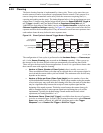
Exposure is controlled by the gate width setting and the number of gates per frame. The
total exposure time is the product of gate width and number of gates per frame. The time of
the opening of the gate is controlled by the delay (i.e., time from trigger to optical opening.)
This is set in WinX or LF. Refer to Chapter 4, First Light, on page 47.
The
MONITOR output may be used with an oscilloscope to determine when the intensifier is
being gated on. The relationship between
MONITOR and optical gate varies depending the
specified gating mode.
• Picosecond Gating
When using picosecond gating, the start of the MONITOR pulse coincides with the
opening of the intensifier, but the width of the
MONITOR pulse is unrelated to the
total intensifier ON time.


