


16 - 65
Chapter 16 Troubleshooting
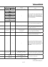
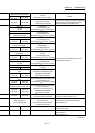
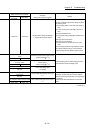
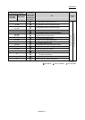
Related buffer memory address
Set range
(Setting with sequence program)
Remedy
QD77MS2
QD77MS4
QD77MS16
1538+100n 4338+100n
<Target position change request flag>
1: Target position change request
• Do not turn ON the target position change request in
the following cases.
1) An operating pattern "continuous path control" is
used.
2) A control system other than ABS1, and INC1 is
used.
3) During deceleration stop.
4) When speed change 0 flag ([Md.31] Status: b10)
is ON.
5) During speed control mode
6) During torque control mode
7) During continuous operation to torque control
mode
• When the target position change address is outside
the software stroke limit range, correct the target
position change address. (Refer to Section 13.5.5)
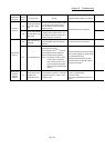
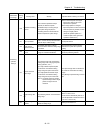
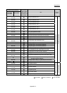
Command torque at torque control
mode
<Command torque at torque control mode>
-10000 to 10000 [
10
-1
%]
Review the setting value so that the setting torque is
not exceeded the torque limit setting value.
1580+100n 4380+100n
Target torque at continuous operation
to torque control
< Target torque at continuous operation to
torque control >
-10000 to 10000 [
10
-1
%]
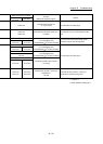
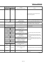
1590+100n 4390+100n
Torque limit setting value
<Torque limit setting value>
1 to 1000[%]
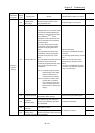
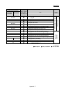
26+150n
Operation setting for speed-torque
control mode
<Torque initial value selection (b4 to b7)>
0, 1
• Use a servo amplifier which supports the servo
parameter "Function selection C-B POL reflection
selection at torque control (PC29)" and set (PC29) to
"1: Disabled".
• Set the torque initial value selection to command
torque.
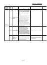
68+150n
POL reflection setting at torque control
<POL reflection setting at torque control>
0, 1
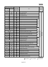
30192+200n 28492+100n
n: Axis No.-1