


10 - 18
Chapter 10 High-Level Positioning Control
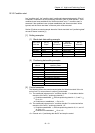
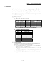
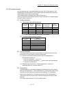
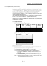
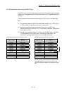
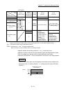
• QD77MS16
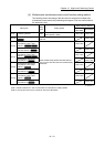
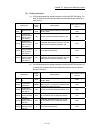
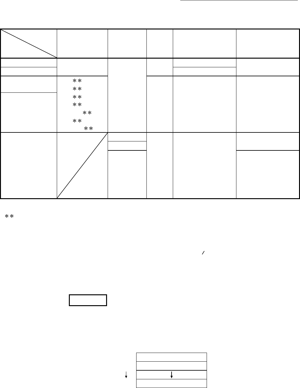
Other setting
item
[Da.15]
Condition target
[Da.16]
Condition operator
[Da.23]
Number of
simultaneously
starting axes
[Da.17]
Address
[Da.18]
Parameter 1
[Da.19]
Parameter 2
01H: Device X
07H : DEV=ON
08H : DEV=OFF
—
—
0 to 1FH (bit No.)
—
02H: Device Y 0 to 1FH (bit No.)
03H: Buffer memory
(1 word)
(Note-1)
01H :
=P1
02H :
P1
03H :
P1
04H :
P1
05H : P1
P2
06H :
P1,
P2
Buffer
memory
address
P1 (numeric value)
P2 (numeric value)
(Set only when "[Da.16]"
is [05H] or [06H].)
04H: Buffer memory
(2 words)
(Note-1)
05H: Positioning data
No.
2
—
Low-order 16 bits:
"[Da.24]
Simultaneously
starting axis No.1"
positioning data No.
High-order 16 bits:
"[Da.25]
Simultaneously
starting axis No.2"
positioning data No.
—
3
4
Low-order 16 bits:
"[Da.26]
Simultaneously
starting axis No.3"
positioning data No.
High-order 16 bits:
Unusable (Set "0".)
– : Setting not required (The setting value is invalid. Set the initial value or a value within the setting range.)
: Value stored in buffer memory designated in [Da.17]
(Note-1): Comparison of
and
is judged as signed values.
Refer to Section 5.5 "List of condition data" for the setting contents.
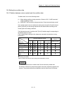
Judgment whether the condition operator is "=" or "
=
” at the start of wait.
Judgment on data is carried out for each operation cycle of the Simple Motion module.
Thus, in the judgment on the data such as current feed value which varies
continuously, the operator "=" may not be detected. If this occurs, use a range operator.
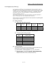
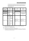
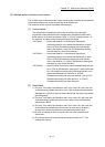
REMARK
The "PLC CPU memo area" can be designated as the buffer memory address to be
designated in [Da.17]. (Refer to Section 7.1.1 "Configuration and roles of QD77MS
memory".)
Address 30000
30001
30099
Simple Motion module
buffer memory