


13 - 63
Chapter 13 Control Sub Functions
[3] Method of setting target position change function from PLC CPU
The following table and chart show the example of a data setting and sequence
program used to change the target position of the axis 1 by the command from
the PLC CPU, respectively. (example in which the target position value and
command speed are changed to a new target position of "300.0
m" and a new
command speed of "10000.00 mm/min".)
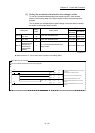
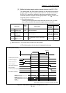
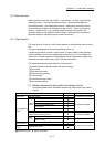
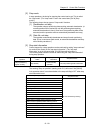
(1) The following data is set.
(Referring to the target position change time chart shown in item (2) below,
carry out the setting with the sequence program shown in item (3).)
Setting item
Setting
value
Setting details
Buffer memory address
QD77MS2
QD77MS4
QD77MS16
[Cd.27]
Target position
change value
(New address)
3000 Set the new address.
1534+100n
1535+100n
4334+100n
4335+100n
[Cd.28]
Target position
change value
(New speed)
1000000 Set the new speed.
1536+100n
1537+100n
4336+100n
4337+100n
[Cd.29]
Target position
change request
flag
1
Set "1: Requests a change in the target
position".
1538+100n 4338+100n
n: Axis No.-1
: Refer to Section 5.7 "List of control data" for details on the setting details.
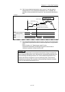
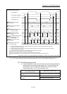
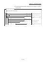
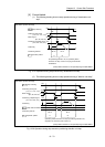
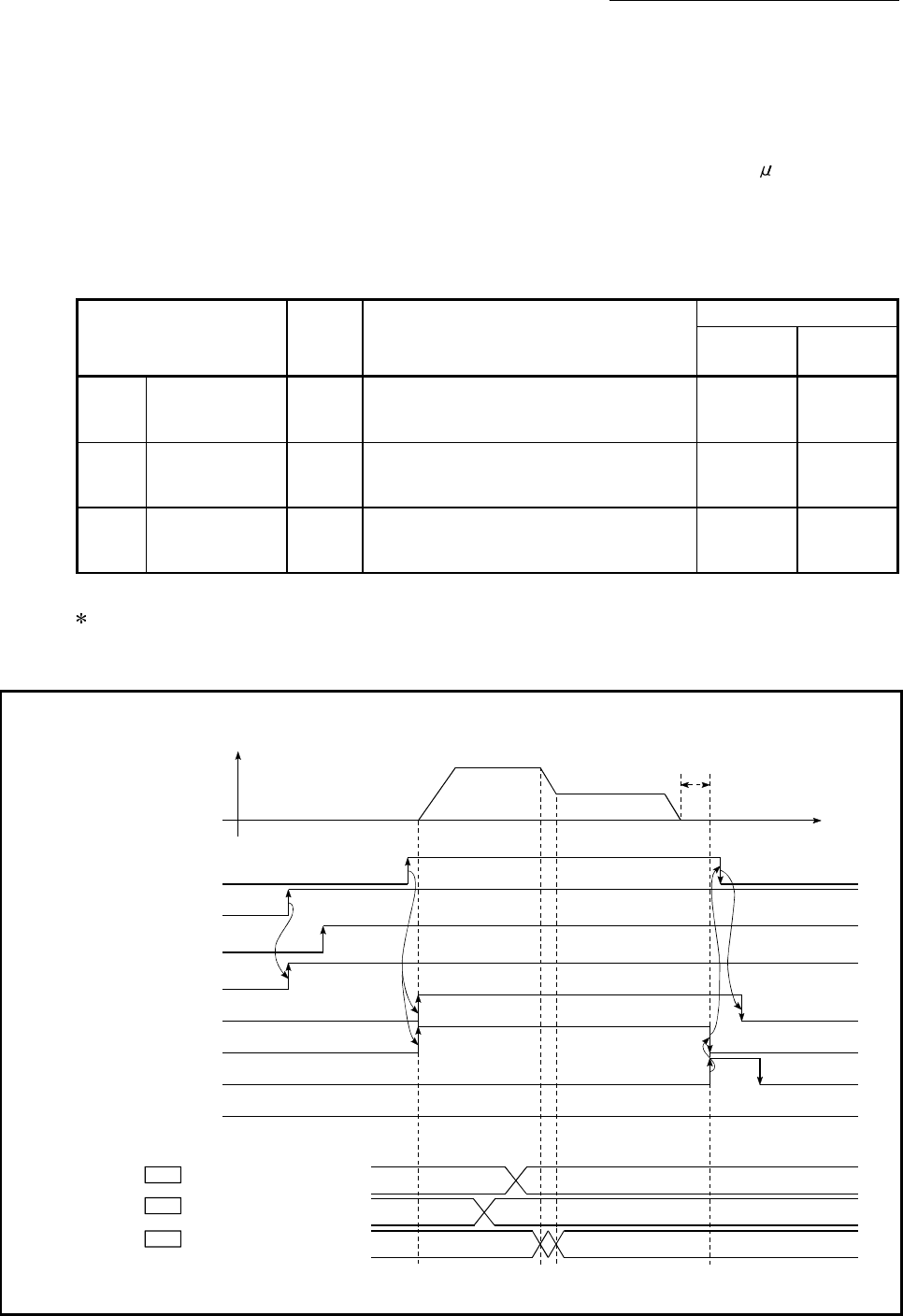
(2) The following shows the time chart for target position change.
[QD77MS4 operation example]
PLC READY signal [Y0]
READY signal [X0]
Start complete signal [X10]
BUSY signal [XC]
Error detection signal [X8]
V
t
Positioning start signal [Y10]
1000000
3000
Positioning complete signal [X14]
Dwell time
Cd.27
Cd.28
1
0
0
Cd.29
All axis servo ON [Y1]
Target position change value
(New address)
Target position change value
(New speed)
Target position change request
flag
(Note): Refer to Section 3.3 for input/output signal of QD77MS16.
Fig. 13.34 Time chart for target position change from PLC CPU