


5 - 70
Chapter 5 Data Used for Positioning Control
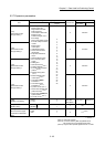
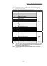
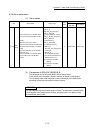
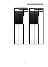
5.2.8 Servo parameters
(1) Servo series
Item Setting details Setting range
Default
value
Buffer memory address
QD77MS2
QD77MS4
QD77MS16
[Pr.100]
Servo
series
Used to select the servo amplifier series
to connect to the Simple Motion module.
[POINT]
• Be sure to set up servo series.
Communication with servo amplifier isn't
started by the initial value "0" in default
value.
(The LED indication of servo amplifier
indicates "Ab".)
• The connectable servo amplifier differs
by the setting of "[Pr.97] SSCNET
setting".
0: Servo series is not set
1: MR-J3-_B
MR-J3W-_B (2-axis type)
3: MR-J3-_B-RJ006
(For fully closed loop control)
MR-J3-_BS (For safety servo)
4: MR-J3-_B-RJ004
(For linear servo)
6: MR-J3-_B-RJ080W
(For direct drive motor)
32: MR-J4-_B
MR-J4W-_B (2-axis type and
3-axis type)
48: MR-JE-_B
64: FR-A700 series (Inverter)
96: VCII series (manufactured by
Nikki Denso Co., Ltd.)
4097: Virtual servo amplifier
(MR-J3)
4128: Virtual servo amplifier
(MR-J4)
0 30100+200n 28400+100n
n: Axis No. -1
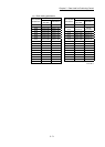
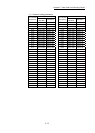
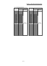
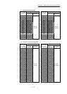
(2) Parameters of MR-J4(W)-B/MR-JE-B
The parameter list for MR-J4(W)-B/MR-JE-B is shown below.
Refer to each servo amplifier instruction manual for details of setting items.
Do not change other than the buffer memory addresses of the parameters
described in each servo amplifier instruction manual.
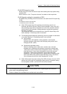
POINT
Set the parameter value and switch power off once (The parameter is transferred to
servo amplifier from Simple Motion module), and then switch it on again to make
that parameter setting valid.