


5 - 44
Chapter 5 Data Used for Positioning Control
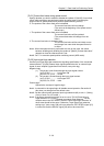
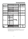
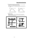
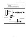
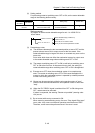
[Pr.36] Sudden stop deceleration time
Set the time to reach speed 0 from "[Pr.8] Speed limit value" ("[Pr.31] JOG speed
limit value" at JOG operation control) during the sudden stop. The illustration
below shows the relationships with other parameters.
When positioning is started,
the acceleration starts following
the "acceleration time".
1) Positioning start
2) Sudden stop cause occurrence
When a "sudden stop cause" occurs,
the deceleration starts following the
"sudden stop deceleration time".
3) Positioning stop
When a "sudden stop cause"
does not occur, the decelera-
tion starts toward the stop
position following the "decel-
eration time".
Actual accel-
eration time
Actual sudden stop
deceleration time
Acceleration time
Actual decel-
eration time
Deceleration time
Speed limit
value
Pr.8
Command
speed
Da.8
Pr.36
Sudden stop
deceleration time
Acceleration time 0
Pr.9
Acceleration time 1
Pr.25
Acceleration time 2
Pr.26
Acceleration time 3
Pr.27
Deceleration time 0
Pr.10
Deceleration time 1
Pr.28
Deceleration time 2
Pr.29
Deceleration time 3
Pr.30
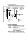
[Pr.37] Stop group 1 sudden stop selection
to
[Pr.39] Stop group 3 sudden stop selection
Set the method to stop when the stop causes in the following stop groups occur.
Stop group 1 ............. Stop with hardware stroke limit
Stop group 2 ............. Error occurrence of the PLC CPU, PLC READY signal
[Y0] OFF, Fault in test mode
Stop group 3 ............. Axis stop signal from PLC CPU
Stop signal from test function of GX Works2
Error occurrence (excludes errors in stop groups 1 and 2:
includes only the software stroke limit errors during JOG
operation, speed control, speed-position switching control,
and position-speed switching control)
The methods of stopping include "0: Normal deceleration stop" and "1: Sudden
stop".
If "1: Sudden stop" is selected, the axis will suddenly decelerate to a stop when the
stop cause occurs.